Sunday, August 31, 2014

12V 15A voltage regulator

- 0 comments

Hear you can see powerful regulator.The pacification of this schema is this one can deliver up to 15 A of current.and also it can give steady 12v current.


Notes

# The T1 can be a 230V AC primary, 18V secondary, 15A type transformer.

# If 15A Bridge is not available, make one using four RURG1520CC diodes.
[Continue reading...]

Saturday, August 30, 2014

2003 Ford Taurus SEL 24 valve V 6 Wiring Diagram

- 0 comments
2003 Ford Taurus SEL 24 valve V 6 Wiring Diagram


This is 2003 Ford Taurus SEL 24 valve V 6 Wiring Diagram: battery, starter solenoid, regulator,
distributor, resistor, safety backup, automatic choke heater, ignition, igniter, spark plugs, air temperature
[Continue reading...]

Preamplifier Circuit Diagram DCF77

- 0 comments
DCF77 Preamplifier Circuit Diagram A popular project among microcontroller aficionados is to build a radio-controlled clock. Tiny receiver boards are available, with a pre-adjusted ferrite antenna, that receive and demodulate the DCF77 time signal broadcast from Mainf lingen in Germany.
DCF77 has a range of about 1,000 miles. All the microcontroller need do is decode the signal and output the results on a display. The reception quality achieved by these ready-made boards tends to be proportional to their price. In areas of marginal reception a higher quality receiver is needed, and a small selective preamplifier stage will usually improve the situation further. 

The original ferrite antenna is desoldered from the receiver module and connected to the input of the preamplifier. This input consists of a source follower (T1) which has very little damping effect on the resonant circuit. A bipolar transistor (T2) provides a gain of around 5 dB. The output signal is coupled to the antenna input of the DCF77 module via a transformer

Circuit diagram: 
Preamplifier
DCF77 Preamplifier Circuit Diagram

DCF77 Preamplifier Circuit Diagram The secondary of the transformer, in conjunction with capacitors C4 and C5, forms a resonant circuit which must be adjusted so that it is centered on the carrier frequency. An oscilloscope is needed for this adjustment, and a signal generator, set to generate a 77.5 kHz sine wave, is also very useful. This signal is fed, at an amplitude of a few milli-volts, into the antenna input. With the oscilloscope connected across C4 and C5 to monitor the signal on the output resonant circuit, trimmer C5 is adjusted until maximum amplitude is observed.

It is essential that the transformer used is suitable for constructing a resonant circuit at the carrier frequency. Our proto-type used a FT50-77 core from Amidon on which we made two 57-turn windings. It is also possible to trim the resonant frequency of the circuit by using a transformer whose core can be adjusted in and out. In this case, of course, the trimmer capacitor can be dispensed with. Rainer Reusch Elektor Electronics 2008
[Continue reading...]

Friday, August 29, 2014

Mobile Car Stereo Player

- 0 comments
Using a mobile phone while driving is dangerous. It is also against the law. However, you can use your mobile phone as a powerful music player with the help of a stereo power amplifier. This does away with the need of a sophisticated in-dash car music system. Most mobile phones have a music player that offers a number of features including preset/manual sound equalisers. They have standard 3.5mm stereo sockets that allow music to be played through standard stereo headphones/sound amplifiers. Nokia 2700 classic is an example. 


Circuit
Mobile Car Stereo Player Circuit Diagram
 
A car audio amplifier with 3.5mm socket can be designed and simply connected to the mobile phone output via a shielded cable with suitable connectors/jacks (readymade 3.5mm male-to-male connector cable is a good alternative). Fig. 1 shows the schema of car stereo player. It is built around popular single-chip audio power amplifier TDA1554Q (IC1). The TDA1554Q is an integrated class-B power amplifier in a 17-lead single-in-line (SIL) plastic power package. 

IC TDA1554Q contains four 11W identical amplifiers with differential input stages (two inverting and two non-inverting) and can be used for single-ended or bridge applications. The gain of each amplifier is fixed at 20 dB. Here it is configured as two 22W stereo bridge amplifiers. The amplifier is powered from the 12V car battery through RCA socket J2. Diode D1 protects against wrong-polarity connection. LED1 indicates the power status. 

Stereo Jack :
3.5mm
(a) 3.5mm stereo socket and (b) 3.5mm Stereo Jack
 
Connect stereo sound signal from the 3.5mm headset socket of the mobile phone to audio input socket J1. When you play the music from your mobile, IC1 amplifies the input. The output of IC1 is fed to speakers LS1 and LS2 fitted at a suitable place in your car. Electrolytic capacitor C5 connected between pin 4 of IC1 and GND improves the supply-voltage ripple rejection. Components R2 and C4 connected at mute/standby pin (pin 14) of IC1 eliminate the switch on/off plop. The schema is quite compact. A good-quality heat-sink assembly is crucial for IC1. Fig. 2 shows the stereo socket and stereo jack. 

Proposed Proposed enclosure

Assemble the schema on a general-purpose PCB and enclose in a suitable cabinet. Small dimensions of the power amplifier make it suitable for being enclosed in a plastic (ABS) case with vent holes. Signal input socket, speaker output terminals, on/off switch, indicator, fuse holder and power supply socket are best located on the front panel of the enclosure as shown in Fig. 3. 

Author : T.K. Hareendran - Copyright : EFY
[Continue reading...]

Thursday, August 28, 2014

Step Up Converter For 20 LEDs

- 0 comments
The schema described here is a step-up converter to drive 20 LEDs, designed to be used as a home-made ceiling night light for a child’s bedroom. This kind of night light generally consists of a chain of Christmas tree lights with 20 bulbs each consuming 1 W, for a total power of 20 W. Here, in the interests of saving power and extending operating life, we update the idea with this simple schema using LEDs. 

Power can be obtained from an unregulated 12 V mains adaptor, as long as it can deliver at least about 330 mA.  The schema uses a low-cost current-mode controller type UCC3800N, reconfigured into voltage mode to create a step-up converter with simple compensation. By changing the external components the schema can easily be modified for other applications. To use a current-mode controller as a voltage-mode controller it is necessary to couple a sawtooth ramp (rising from 0 V to 0.9 V) to the CS (current sense) pin, since this pin is also an input to the internal PWM comparator.


Step-up
Step-up Converter For 20 LEDs Circuit Diagram

The required ramp is present on the RC pin of the IC and is reduced to the correct voltage range by the voltage divider formed by R3 and R2. The RC network formed by R4 and C6 is dimensioned to set the switching frequency at approximately 525 kHz. The comparator compares the ramp with the divided-down version of the output voltage produced by the potential divider formed by R6 and R7. Trimmer P1 allows the output voltage to be adjusted. This enables the current through the LEDs to be set to a suitable value for the devices used. The UCC3800N starts up with an input voltage of 7.2 V and switches off again if the input voltage falls below 6.9 V. The schema is designed so that output voltages of between 20 V and 60 V can be set using P1.

This should be adequate for most cases, since the minimum and maximum specified forward voltages for white LEDs are generally between 3 V and 4.5 V. For the two parallel chains of ten LEDs in series shown here a voltage of between 30 V and 45 V will be required. The power components D1, T1 and L1 are considerably over specified here, since the schema was originally designed for a different application that required higher power. To adjust the schema, the potentiometer should first be set to maximum resistance and a multimeter set to a 200 mA DC current range should be inserted in series with the output to the LEDs. Power can now be applied and P1 gradually turned until a constant current of 40mA flows. The step-up converter is now adjusted correctly and ready for use.
[Continue reading...]

Wednesday, August 27, 2014

DCF77 to USB Converter

- 0 comments
I like the handy DCF77 signal. In this project no clock should use it, instead the computers in my home network should be served by a precise time reference. Due to the fact most other interfaces are no longer available on modern computers, it uses the USB to forward the prepared DCF77 signal to the host. [Link]

DCF77 to USB Converter
[Continue reading...]

500W Inverter 12 Volt to 220 Volt Circuit Diagram

- 0 comments
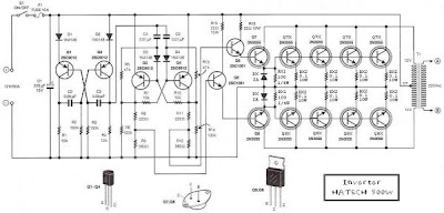
This is the Simple 500W Inverter 12 Volt to 220 Volt Circuit Diagram about the the inverter, because like working outdoors, or to backup storage to use when necessary. Most of this is circuit low power, which is not suitable for practical applications. My friends said that he would be about 500 Watt. It is a good size. Use with television receivers and light bulbs as well. When looking for circuit. I get headaches. 

500W Inverter 12 Volt to 220 Volt Circuit Diagram
 
500W Inverter 12 Volt to 220 Volt Circuit Diagram

If you are a beginner or I can not buy expensive good quality circuits. Requires only one transistor. Or if you have free time. I want to build old circuit is alive again. This circuit will accommodate all your needs. It is a simple circuit. The same principle, I take battery voltage 12V to produce a oscillator about 100 Hz and pass to a two frequency divider circuit is only 50HZ. and drive a 10 ampere transformer with 10 x 2N3055 transistor in parallel. 

By a single transistor has 2A, when I use 10 transistors or 5 pairs of drive high current output. The complexity of circuit, but the principle is not it, and it is the number of transistors on a basic, easy to buy. You may be modified 100 watt power inverter To the size of transistors and transformers as well. 

Note:
If you think that This circuit is not good enough. For your work. It is hard to find equipment. You do not have it now. These circuits may be viewed below. It may be appropriate for you.


Source: leksound project

[Continue reading...]
 
Copyright © 2012. Fast Diagrams - Posts · Comments
Powered by Blogger