Thursday, November 20, 2014

Circuit of fire alarm detection

- 0 comments
The rooms are vulnerable to fire as a storage material, flammable, requires a system to prevent the occurrence of a fire. For example, using a fire alarm detection, so for example occur if a flame that can quickly and others that are easily fire did not cause a fire is greater.

Here is a simple alarm circuit is based on the LDR and the lamp of a pair of smoke alarm sensors fire.The sensor works produced fire.The circuit produces an alarm when a fire smoke.


Fire alarm detector Components :

  • The speaker can be 8Ω tweeter.
  • POT R4 can be used to adjust the sensitivity of the alarm.
  • POT R3 can be used to vary the volume of the alarm.
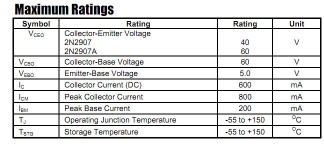
  • Any general purpose NPN transistor (BC548, BC148, 2N222) can be used for Q1.
  • The circuit can be powered by a 9V battery or 9V DC power supply.
  • On the contrary, it is bright LED bulb 1K resistor in series on it.
Where there is smoke from the bulb will drop directly LDR.The LDR resistance is low and hence the voltage across its terminals (less than 0.6 V). The transistor is blocked and no happens.When there is enough smoke to obscure the light falls on the LDR, LDR resistance increases and the fact that the voltage across the transistor passes it.Now ON.This feeds IC1 and the output 5V.This power tone generator IC UM66 (IC2) to play music for music will be amplified by IC3 (AD 2002) to drive the speaker.

The diode D1 and D2 in combination drops to 1.4 V for the nominal voltage (3.5 V) to the UM66. UM 66 can not support more than 4V.
[Continue reading...]

Wednesday, November 19, 2014

USB Audio Interface based DAC PCM2902

- 0 comments

This is the circuit quality preamplifier with built-in USB DAC for my Leachamp power amplifier. Scheme is PCM2902 datasheet. Circuit includes DAC and ADC, SPDIF input and output of HID and with 3 buttons + MUTE, VOL-and VOL.

For playback of high quality needed for external low-drop voltage stabilizer for the DAC. LP2951CM DAC is used, which was readily available in local stores. Output voltage is fixed at about 3.7 V with two resistors. Circuit board is designed with regard to the placement of good land, and the separation of digital and analog ground. These earth are connected in a single point in a USB connector.


The PCM2902 data sheet is recommended to connect a low pass filter the DAC output to filter high frequencies above audioband produced by the conversion of oversampling. Digital integrated circuits that includes LPF filter frequency above 100 kHz. In the Notes application filter on the pages of the manufacturer recommends first-order LPF (simple RC) or 2 nd order with amplifiers operating as a preamp that works well. I simple RC LPF with the recommended values ​​R and C 1k 4N7. It is best to use the scroll-type ceramic capacitor in place. I did not hear the difference in sound between the connection filter or not, but with respect to other components in an audio chain is best used. For maximum cutoff frequency that can change the capacitor value of 3n3
[Continue reading...]

Power Supply Failure Alarm

- 0 comments
Most of the circuit power supply failure alarm circuits require additional or external power supply. However, this circuit requires no additional power supply. The circuit uses a voltage of 5 volts to 15 volts. To adjust the voltage of this circuit, first connect the power source (5 to 15V) and change the position of potentiometer VR1 until the buzzer buzzer On to Off position.
If the power supply fails, resistor R2 will bias the transistor and the base will turn on the buzzer. Here is a picture series of power supply failure alarm :
 power supply failure alarm
 Power Supply Failure Alarm  Circuit

[Continue reading...]

Tuesday, November 18, 2014

20W Surround audio amplifier with SI 1020G

- 0 comments
Have you been use the IC above? if those who have not, IC above is used or applied to the audio power amplifier. IC processing is quite good for use on amplifier home, or room. IC used is SI1020G who have not very high output with only 20W 8 ohm impedance speakers. Supply voltage ranging from 12 volt to 23 volts.


Below schematic audio amplifier with IC SI1020G
Part List
R1 = 100K
R2 = 1R
C1 = 2u2F
C2 = 100uF
C3 = 47uF
C4 = 10uF
C5 = 2200uF
C6 = 47uF
C7 = 100uF 
[Continue reading...]

Monday, November 17, 2014

Hot Water Level Indicator

- 0 comments

Notes:
Save fuel bills and the economy of the planet with this circuit. SW1 is a normally open press button switch which allows you to view the level of hot water in a hot water tank. When pressed the voltage difference at the junction of the thermistor and preset is compared to the fixed voltage on the op-amps non-inverting input. Depending on the heat of the water in the tank, the thermistors resistance will toggle the op-amp output to swing to almost full voltage supply and light the appropriate LED.

Construction:
Masking tape was used to stick the bead thermistors to the tank. Wires were soldered and insulated at the thermistors ends. A plastic box was used to house the circuit. Battery life will probably be 4 to 5 years depending on how often you use the push switch, SW1.

Sensor Placement:
Thermistors NTC1-4 should be spread evenly over the height of the tank. I placed NTC1 roughly 4 inches from the top of my tank and the others were spaced evenly across the height of the hot water tank. As hot water rises the lowest sensor indicates the fullest height of hot water and should be about 8 to 10 inches from the bottom of the tank.

Calibration:
With a full tank of hot water adjust P1-4 so that all LEDs are lit. As hot water rises, the sensor at the bottom of the tank will be the maximum level of hot water. "Hot" can be translated as 50C to 80C the presets P1-4 allow adjustment of this range.

Parts:

I have used a quad version of the LM324 but any quad opamp can be used or even four single op-amps.
R2-R5 I used 330ohm resistors, but value is not critical. Lower values give brighter LED output.
NTC1-4 The thermistors maximum resistance must roughly equal the resistance of the fixed resistor and preset. As negative temparature coefficient (NTC) thermistors are used, then their resistance decreases for increases in temperature. I used a thermistor from the Maplin Catalogue. Cold resistance was around 300K, hot resistance 15k. Alternative thermistors may be used with different resistance ranges, but the presets P1 to P4 must also be changed as well.

R7-10 series resistance, only required if your thermistors resistance is several ohms at the hottest temperature.
P1 - P4 Chosen to match the resistance of the thermistor when cold.
R1 & R6. These resistors are equal and bias the op-amp inverting input to half the supply voltage. I used 100k.
[Continue reading...]

Sunday, November 16, 2014

Automatic Water Pump Controller

- 0 comments
Automatic water pump controller is a series of functions to control the water pump otamatis in a reservoir or water storage. As the water level sensor made with a metal plate mounted on the reservoir or water tank, with a sensor in the short to create the top level and a detection sensor for detecting long again made the lower level and ground lines connected to the bottom of reservoirs or reservoir. The series of automatic water pump controller is designed with 2 inputs NOR by 4 pieces and relay that is activated by the transistor. Automatic water pump circuit requires +12 VDC voltage source and can be used to control the water pump is connected to AC power jalringan. Here is the complete series of pictures.

Series Automatic Water Pump Controller


Sign Component Automatic Water Pump Controller
R1 = 15K
R2 = 15K
R3 = 10K
R4 = 1K
D1 = LED
D2 = 1N4148
Q1 = BC337
IC1 = 4001
SW = SPDT Switches
Relay RL1 = 12V

The working principle series of automatic water pump controller above is. At the time the water level is below both sensors, the output IC1C (pin 10) will be LOW, Kemudin when the water began to touch the lower level sensor, the output IC1C (pin10) remains LOW until the water touches the sensor level above, then the output IC1C (pin 10) going HIGH and active relay through Q1 and turn on the water pump to meguras reservoir. At the muli down and water level sensors for water untouched MKA IC1C output (pin 10) remains HIGH until the new water untouched semuasensor IC1C output (pin 10) LOW and water pump died. The series of automatic water pump controller is equipped with SW1 which serves to reverse the logic of drains (the output of IC1C) and the concept of water supplied (output dri IC1D). When SW1 is connected to IC1D the water pump will turn on when the water does not touch all the sensors and will die when all the sensors tesentuh water. Automatic water pump controller can be used to fill or drain the water according to which mode is selected via SW1.
[Continue reading...]

Saturday, November 15, 2014

Parts Needed for Motion Detector Circuit

- 0 comments
This is a circuit which can detect any motion or movement. Its most common use is to detect a person moving through an area where the motion detector can sense.

For example, the motion detector may be placed near a door, so that if any person passes through this doorway, the motion detector will be triggered.

The main electronic component we will use that allows us to pick up this detection is the PIR motion sensor. The PIR motion sensor is a sensor which detects movement through picking up infrared waves. Being that a person emits infrared waves, the detector is able to detect these waves and react, according to the how the circuit is designed to react. The sensor can also pick up the movement of inanimate objects as well, such a rolling ball, because as those objects move, friction acts on them, generating heat. This heat emits infrared radiation, which the PIR sensors may be able to detect if great enough.

In our basic circuit, when the motion detector circuit picks up movement, a red LED will flicker on. 

Parts Needed for Motion Detector Circuit
  • PIR motion sensor
  • LED
  • 470Ω Resistor
  • 6V of DC power

The PIR motion sensor is, again, a sensor which can detect movement through picking up infrared radiation. Being that people naturally give off radiation, because of our generated body heat, the motion can easily detect people walking and moving through a vicinity within the sensors range.

The motion sensor has a sensitivity range up to 20 feet (6 meters) and a 110° x 70° detection range, making it a wide lens detection sensor. This means it can measure 110° vertically (from top to bottom) and 70° horizontally (from left to right). The best way to check its sensitivity is when the circuit is built, try moving around through all of its angles. See at which angles it can detect your movement and at which angles it is not able to detect your movement, meaning your out of its angle scope. A lot of it is trial and error and experimenting. Once you know where it can and cannot detect, you can place it in an optimal place where it can detect in areas where you want it to.

The PIR motion sensor is a 3-pin device

Pin 1 is the pin which receives the positive DC voltage. The PIR motion sensor needs between 5V-9VDC of power for operation. In our case, we will use about 6V of power. This can be obtained from switching a DC power supply to 6V or using 4 AA batteries connected in series. We will then feed this voltage into pin 1 of the PIR module.

Pin 3 is the negative DC voltage or ground pin of the device. We connect the negative terminal of the power source to this pin, for a return path.

Pin 2 is the Output pin of the PIR module. This is where the output of the PIR will leave from. When motion is detected by the PIR, its output will go high to 3V. When no motion is detected, its output low and it gives off practically no voltage. When high you can see then how it can power a load, such as an LED to light. This way we can know when it has detected motion or not.

In our circuit, we will connect a 470Ω resistor in series with an LED to the output pin of the PIR sensor. When motion is detected, the output of the PIR sensor will swing high and power and light the LED.

Circuit Diagram
Here you can see anywhere from 5V-9V is fed into the power pins.

Connected to the output pin is an LED. We place a 470Ω resistor in series to limit current so that the LED doesnt receive excess current.

In this circuit, when motion is detected, the output voltage swings high and powers the LED. After about 1 second or 2, the output swings back low and the LED turns off until motion is detected again. Without any motion, the LED just stays off.
[Continue reading...]

Thursday, November 13, 2014

How to Build 12 Volt DC Fluorescent Lamp

- 0 comments
A number of people have been unable to find the transformer needed for the Black Light project, so I looked around to see if I could find a fluorescent lamp driver that does not require any special components. I finally found one in Electronics Now. Here it is. It uses a normal 120 to 6V stepdown transformer in reverse to step 12V to about 350V to drive a lamp without the need to warm the filaments.12 Parts:C1 100uf 25V Electrolytic Capacitor
C2,C3 0.01uf 25V Ceramic Disc Capacitor
C4 0.01uf 1KV Ceramic Disc Capacitor
R1 1K 1/4W Resistor
R2 2.7K 1/4W Resistor
Q1 IRF510 MOSFET
U1 TLC555 Timer IC
T1 6V 300mA Transformer
LAMP 4W Fluorescent Lamp
MISC Board, Wire, Heatsink For Q1Notes:
  1. Q1 must be installed on a heat sink.
  2. A 240V to 10V transformer will work better then the one in the parts list. The problem is that they are hard to find.
  3. This circuit can give a nasty (but not too dangerous) shock. Be careful around the output leads.
[Continue reading...]

Wednesday, November 12, 2014

Pump Controller For Solar Hot Water System

- 0 comments
This circuit optimises the operation of a solar hot water system. When the water in the solar collector is hotter than the storage tank, the pump runs. The circuit comprises two LM335Z temperature sensors, a comparator and Mosfet. Sensor 1 connects to the solar collector panel while Sensor 2 connects to the hot water panel. Each sensor includes a trimpot to allow adjustment of the output level. In practice, VR1 and VR2 are adjusted so that both Sensor 1 and Sensor 2 have the same output voltage when they are at the same temperature. The Sensor outputs are monitored using comparator IC1.

When Sensor 1 produces a higher voltage than Sensor 2, which means that sensor 1 is at a higher temperature, pin 1 of IC1 goes high and drives the gate of Mosfet Q1. This in turn drives the pump motor. IC1 includes hysteresis so that the output does not oscillate when both sensors are producing a similar voltage. Hysteresis comprises the 1MO feedback resistor between output pin 1 and non-inverting input pin 3 and the input 1kO resistor. This provides a nominal 12mV hysteresis so that voltage at Sensor 1 or Sensor 2 must differ by 12mV for changes in the comparator output to occur.

Circuit diagram:


Since the outputs of Sensor 1 and Sensor 2 change by about 10mV/°C, we could say that there is a degree of hysteresis in the comparator. Note that IC1 is a dual comparator with the second unit unused. Its inputs are tied to ground and pin 2 of IC1 respectively. This sets the pin 7 output high. Since the output is an open collector, it will be at a high impedance. Mosfet Q1 is rated at 60A and 60V and is suitable for driving inductive loads due to its avalanche suppression capability. This clamps any inductively induced voltages exceeding the voltage rating of the Mosfet.

The sensors are adjusted initially with both measuring the same temperature. This can be done at room temperature; adjust the trimpots so that the voltage between ground and the positive terminal reads the same for both sensors. If you wish, the sensors can be set to 10mV/°C change with the output referred to the Kelvin scale which is 273K at 0°C. So at 25°C, the sensor output should be set to (273 + 25 = 298) x 10mV or 2.98V.Note:The sensors will produce incorrect outputs if their leads are exposed to moisture and they should be protected with some neutral cure silicone sealant. The sensors can be mounted by clamping them directly to the outside surface of the solar collector and on an uninsulated section of the storage tank. The thermostat housing is usually a good position on the storage tank.
Author: John Clarke - Copyright: Silicon Chip Electronics
[Continue reading...]

PIC12F675 and PIC12F629 datasheet

- 0 comments
PIC12F629 and PIC12F675 are 8-Pin Flash-Based 8-Bit CMOS Microcontrollers. The PIC12F629 and PIC12F675 devices are identical, except the PIC12F675 has a 10-bit A/D converter. They come in 8-pin PDIP, SOIC, MLF-S and DFN packages.High-Performance RISC CPU:
 pic12f675 and pic12f629 datasheet
  • Only 35 Instructions to Learn
    • All single-cycle instructions except branches
  • Operating Speed:
    • DC – 20 MHz oscillator/clock input
    • DC – 200 ns instruction cycle
  • Interrupt Capability
  • 8-Level Deep Hardware Stack
  • Direct, Indirect, and Relative Addressing modes
PIC12F629/675 Special Microcontroller Features:
  • Internal and External Oscillator Options
  • Power-Saving Sleep mode
  • Wide Operating Voltage Range – 2.0V to 5.5V
  • Industrial and Extended Temperature Range
  • Low-Power Power-on Reset (POR)
  • Power-up Timer (PWRT) and Oscillator Start-up Timer (OST)
  • Brown-out Detect (BOD)
  • Watchdog Timer (WDT) with Independent Oscillator for Reliable Operation
  • Multiplexed MCLR/Input Pin
  • Interrupt-on-Pin Change
  • Individual Programmable Weak Pull-ups
  • Programmable Code Protection
  • High Endurance Flash/EEPROM Cell
PIC12F629/675 datasheet
[Continue reading...]

Saturday, November 8, 2014

Class AB Power Amplifier Circuit 30w Using Power Transistor

- 0 comments


30W Class AB power amplifier circuit diagram using power transistor. Set the above amplifier up by adjust the variable resistor R1 to maximum and R12 to zero. After this set up is done, the activate / turn on the amplifier. Adjust the R1 so that the measured output offset is between 30 and 100mV. Once set, adjust the R12 slowly to achieve a quiescent current of around 120mA. Keep checking the quiescent current as the amplifier heats up as it might change due to voltage drop changes in the output devices because of the heat. The heatsinks should be 0.6K/W or less for two amplifiers.

Power supply circuit for 30W class AB power amplifier:
power
30W Class AB Power Amplifier Circuit 
[Continue reading...]

Simple Cheap LED flasher

- 0 comments

This two LED flasher circuit uses any DC supply from 3V to 12V. Flash rate is controlled by R1,C1 and R2,C2. Larger values create slower fash rates, smaller values higher flash rates.
[Continue reading...]

Wednesday, November 5, 2014

Petrol Diesel Level Sensor

- 0 comments
This sensor is particularly suitable for use in small spaces, such as the petrol tank of a  motorbike. It has the advantage of not having any moving parts, unlike a conventional sensor with a float and float arm that make it difficult to fit in a tank.

The sensor circuit is made from standard, inexpensive components and can be put together for little money.

Petrol/Diesel Level Sensor Circuit diagram :

Sensor-Circuit


The operating principle is  based on  measuring  the forward volt-ages of two identical diodes (check this  first by measuring  them).  The forward voltage of a diode decreases with increasing junction temperature. lf a resistor is placed close to one of the two diodes, it will be heated slightly if it extends above the surface of the  petrol. For best results,the other diode (used for reference) should be located at the same level. lf the diodes are covered by the petrol in the tank, the heating resistor will not have any effect because it will be cooled by the petrol. An opamp compares the voltage across the two diodes, with a slightly smaller current passing through the reference diode. 

When the petrol level drops, the output of the opamp goes high and the output transistor switches on. This causes a sense resistor to be connected in parallel with the sensor output. Several sensor circuits can be used together, each with its own switched sense resistor connected in parallel with the output, and the resulting output  signal can be used to drive a meter or the like.

Using this approach, the author built a petrol tank sensors trip tank consisting of five PCBs, each fitted with two sensor circuits. With this sensor strip installed at an angle in the tank, a resolution of approximately 1.5 litre per sensor is possible. Many tanks have an electrical fitting near the bottom for connection to a lamp on the instrument panel that indicates the reserve level. The sensor strip can be used in its place. You will have to experiment a bit with the values of the sense resistors, but do not use values lower than around100 O. It is also important to fit the diodes and heater resistor in a little tube with a small opening at the bottom so that splashing petrol does not cool the heater resistor, since this would result in false readings.

The circuit should be powered from a regulated supply voltage of 5 to 6 V to prevent the heating resistors from becoming too hot. After testing everything to be sure that it works properly, its a good idea to coat the circuit board with epoxy glue to provide better protection against the petrol.

Tip: you can use the well-known 1M3914 to build a LED display with ten LEDs, which can serve as a level indicator. Several examples of suitable circuits can be found in back issues of Elektor.

Note: this sensor circuit is not suitable for use in conductive liquids.
[Continue reading...]

Simple and Mini FM Receiver

- 0 comments
This is a very simple and mini fm radio receiver with good performances that works great even if the sensitivity is not too high. The working principle of this fm receiver may seem a little unusual. It is made of an oscillator (T2 and T3) that is synchronized with the received frequency of T1. This transistor works as a broadband preamplifier in VHF range.

Mini FM Receiver Circuit Diagram :

FM

The oscillator is adjusted between 87 … 108 MHz with C5. Because of the synchronization, the oscillator output will have the same frequency deviation as the received signal from the fm antenna. This deviations are caused by the broadcasted audio informations. The frequency modulated signal show up on P1 + R5. Low pass filter R6/C6 extracts the audio signal and then is amplifier by T4 … T6 and transmitted at the output through C9 capacitor.

The coil details are presented in the fm receiver circuit diagram. The radio receiver is adjusted on different stations with the help of C5. P1 potentiometer is adjusted untill the best reception is obtained. If we attach an audio amplifier and a speaker then this fm receiver can be made very compact as a pocket radio.


[Continue reading...]

Tuesday, November 4, 2014

1997 Chevrolet Z34 Monte Carlo Diagram

- 0 comments
Diagram for removing the headlamp assembly 1997 Chevrolet Z34 Monte Carlo  
  1. Radiator air side baffle from radiator air upper baffle.
  2. Upper fascia push-in retainer.
  3. Thumbscrews from upper headlamp.
  4. Headlamp, while pulling back fascia horn, slide headlamp inboard to disengage upper and lower outboard tabs.
  5. Electrical connectors.
  6. Headlamp from vehicle.
  7. Socket and bulb from headlamp.
More info chevrolet here
[Continue reading...]

Preamp Stage For Ceramic Phono Cartridge Or Violin Pickups

- 0 comments
While we have published a number of variations on a standard RIAA preamplifier for magnetic phono cartridges, we have not published a preamp stage for ceramic phono cartridges. Typically, these were supplied as turnover cartridges in record changers but there were higher quality versions such as the Decca Deram. These phono cartridges are piezoelectric devices which require a very high input impedance. Similarly, violin pick-ups made by Fishman, Barcus Berry and others are piezo devices. These two circuits have been requested for a violin pickup but could equally well suit a ceramic or crystal pickup. The op amp circuit uses a TL071 connected as a voltage-follower. It can run from a battery supply of ±9V.

Circuit diagram:

preamp-stage-for-ceramic-phono-cartridge-or-violin-pickup

The alternative transistor circuit uses a BC549 connected as an emitter-follower but with bootstrapping of the input bias network to provide a high input impedance. Both circuits have input coupling capacitors but since the transducers are capacitive (ie, piezo) they could possibly be omitted. Both circuits will probably need to be followed by further gain, depending on the output level. For a violin pickup, a parametric equaliser is also recommended, and for this we would suggest the 3-band parametric equaliser published in the July 1996 issue of SILICON CHIP. With a slight change to the feedback of the first op amp in this circuit, the extra gain required could also be provided.


[Continue reading...]

Monday, November 3, 2014

2N2907A datasheet

- 0 comments
Features 
•   High current (max.600mA) 
•   Low voltage (max.60V) 
 •  Lead Free Finish/RoHS Compliant(Note 1) ("P" Suffix designates RoHS Compliant.  See ordering information) 

DESCRIPTION                                                      
The 2N2905A and 2N2907A are silicon Planar Epitaxial PNP transistors in Jedec TO-39 (for 2N2905A) and in Jedec TO-18 (for 2N2907A)
metal case. They are designed for high speed saturated switching and general purpose applications.

[Continue reading...]

Sunday, November 2, 2014

1 5V POWERED LED FLASHER ELECTRONIC DIAGRAM

- 0 comments
1.5V POWERED LED FLASHER ELECTRONIC DIAGRAM

It is a charge pump design. This is where a capacitor (electrolytic) is allowed to charge and is then raised higher and allowed to discharge into a load. The load sees a voltage that can be higher than the supply.
[Continue reading...]

ic 555 Infra red Light Barrier Diagram Circuit

- 0 comments
This is a short-range light barrier for use as an intruder alarm in doorposts, etc. The 555 in the transmitter (Figure 1) oscillates at about 4.5 kHz, supplying pulses with a duty cycle of about 13% to keep power consumption within reason. Just about any infra-red LED (also called IRED) may be used. Suggested, commonly available types are the LD271 and SFH485. The exact pulse frequency is adjusted with preset P1. The LEDs are pulsed at a peak current of about 100 mA, determined by the 47 Ω series resistor. In the receiver (Figure 2), the maximum sensitivity of photo-diode D2 should occur at the wavelength of the IR LEDs used in the transmitter. You should be okay if you use an SFH205F, BPW34 or BP104. Note that the photo-diode is connected reverse-biased! So, if you measure about 0.45 V across this device, it is almost certainly fitted the wrong way around.

transmitterThe received pulses are first amplified by T1 and T2. Next comes a PLL (phase lock loop) built with the reverenced NE567 (or LM567). The PLL chip pulls its output, pin 8, Low when it is locked onto the 4.5 kHz ‘tone’ received from the transmitter. When the (normally invisible) light beam is interrupted (for example, by someone walking into the room), the received signal disappears and IC1 will pull its output pin High. This enables oscillator IC2 in the receiver, and an audible alarm is produced. The two-transistor amplifier in the receiver is purposely over-driven to some extent to ensure that the duty cycle of the output pulses is roughly 50%.

ReceiverIf the transmitter is too far away from the receiver, over-driving will no longer be guaranteed, hence IC1 will not be enabled by an alarm condition. If you want to get the most out of the circuit in respect of distance covered, start by modifying the value of R2 until the amplifier output signal again has a duty cycle of about 50%. The circuit is simple to adjust. Switch on the receiver, the buzzer should sound. Then switch on the transmitter. Point the transmitter LEDs to the receiver input. Use a relatively small distance, say, 30 cm. Adjust P1 on the transmitter until the buzzer is silenced. Switch the receiver off and on again a few times to make sure it locks onto the transmitter carrier under all circumstances. If necessary, re-adjust P1, slowly increasing the distance between the transmitter and the receive
[Continue reading...]
 
Copyright © 2012. Fast Diagrams - Posts · Comments
Powered by Blogger