Showing posts with label 12. Show all posts

Thursday, November 13, 2014

How to Build 12 Volt DC Fluorescent Lamp

- 0 comments
A number of people have been unable to find the transformer needed for the Black Light project, so I looked around to see if I could find a fluorescent lamp driver that does not require any special components. I finally found one in Electronics Now. Here it is. It uses a normal 120 to 6V stepdown transformer in reverse to step 12V to about 350V to drive a lamp without the need to warm the filaments.12 Parts:C1 100uf 25V Electrolytic Capacitor
C2,C3 0.01uf 25V Ceramic Disc Capacitor
C4 0.01uf 1KV Ceramic Disc Capacitor
R1 1K 1/4W Resistor
R2 2.7K 1/4W Resistor
Q1 IRF510 MOSFET
U1 TLC555 Timer IC
T1 6V 300mA Transformer
LAMP 4W Fluorescent Lamp
MISC Board, Wire, Heatsink For Q1Notes:
  1. Q1 must be installed on a heat sink.
  2. A 240V to 10V transformer will work better then the one in the parts list. The problem is that they are hard to find.
  3. This circuit can give a nasty (but not too dangerous) shock. Be careful around the output leads.
[Continue reading...]

Monday, September 22, 2014

12 Volt 30 Amp PSU circuit and explanation

- 0 comments

Using a single 7812 IC voltage regulator and multiple outboard pass transistors, this power supply can deliver output load currents of up to 30 amps. The design is shown below:

Circuit diagram

Notes:
The input transformer is likely to be the most expensive part of the entire project. As an alternative, a couple of 12 Volt car batteries could be used. The input voltage to the regulator must be at least several volts higher than the output voltage (12V) so that the regulator can maintain its output. If a transformer is used, then the rectifier diodes must be capable of passing a very high peak forward current, typically 100amps or more. The 7812 IC will only pass 1 amp or less of the output current, the remainder being supplied by the outboard pass transistors. As the circuit is designed to handle loads of up to 30 amps, then six TIP2955 are wired in parallel to meet this demand. The dissipation in each power transistor is one sixth of the total load, but adequate heat sinking is still required. Maximum load current will generate maximum dissipation, so a very large heat sink is required. In considering a heat sink, it may be a good idea to look for either a fan or water cooled heat sink. In the event that the power transistors should fail, then the regulator would have to supply full load current and would fail with catastrophic results. A 1 amp fuse in the regulators output prevents a safeguard. The 400mohm load is for test purposes only and should not be included in the final circuit. A simulated performance is shown below:

Calculations:
This circuit is a fine example of Kirchoffs current and voltage laws. To summarise, the sum of the currents entering a junction, must equal the current leaving the junction, and the voltages around a loop must equal zero. For example, in the diagram above, the input voltage is 24 volts. 4 volts is dropped across R7 and 20 volts across the regulator input, 24 -4 -20 =0. At the output :- the total load current is 30 amps, the regulator supplies 0.866 A and the 6 transistors 4.855 Amp each , 30 = 6 * 4.855 + 0.866. Each power transistor contributes around 4.86 A to the load. The base current is about 138 mA per transistor. A DC current gain of 35 at a collector current of 6 amp is required. This is well within the limits of the TIP2955. Resistors R1 to R6 are included for stability and prevent current swamping as the manufacturing tolerances of dc current gain will be different for each transistor. Resistor R7 is 100 ohms and develops 4 Volts with maximun load. Power dissipation is hence (4^2)/200 or about 160 mW. I recommend using a 0.5 Watt resistor for R7. The input current to the regulator is fed via the emitter resistor and base emitter junctions of the power transistors. Once again using Kirchoffs current laws, the 871 mA regulator input current is derived from the base chain and the 40.3 mA flowing through the 100 Ohm resistor. 871.18 = 40.3 + 830. 88. The current from the regulator itself cannot be greater than the input current. As can be seen the regulator only draws about 5 mA and should run cold.


author:
e-mail:
web site: http://www.mitedu.freeserve.co.uk/
[Continue reading...]

Wednesday, September 17, 2014

12 12W STEREO AMPLIFIER WITH MUTING

- 0 comments
12 +12W STEREO AMPLIFIER WITH MUTING


[Continue reading...]

Tuesday, September 2, 2014

Simple 12 Volt Charger Wiring diagram Schematic with LM350

- 0 comments
Simple 12 Volt Charger Circuit Diagram with LM350.The strength supply routine structure is developed as a resource of continuous present with adverse heat range coefficient. Transistor Q1 (BD 140) is used as a heat range indicator. transistor Q2 is used to avoid the strength supply from discharging through R1 when strength is out of stock. Getting routine is developed depending on the LM350 present regulator IC. The result present of the battery charger can be altered between 13-15 V by various the POT R6.

 Simple 12 Volt Charger Circuit Diagram with LM350


LM350 will try to keep the present decrease between the feedback pin and result pin at a continuous value of 1.25V. So there will be a continuous present circulation through resistor R1. Q1 act here as a heat range indicator with the help of R6/R3/R4 elements that are more or less manages the platform present of Q1. As relationship emitter / platform of transistor Q1, the same as other semiconductors, containing the heat range coefficient of-2mV / ° C, the present result will also display a bad heat range coefficient. This one is just a aspect of 4 huge, because the difference of the emitter / platform of Q1 is increased by a aspect of category P1/R3/R4. This causes some-8mV / ° C. LED will lighting whenever strength is available.
[Continue reading...]

Wednesday, August 27, 2014

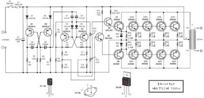
500W Inverter 12 Volt to 220 Volt Circuit Diagram

- 0 comments
This is the Simple 500W Inverter 12 Volt to 220 Volt Circuit Diagram about the the inverter, because like working outdoors, or to backup storage to use when necessary. Most of this is circuit low power, which is not suitable for practical applications. My friends said that he would be about 500 Watt. It is a good size. Use with television receivers and light bulbs as well. When looking for circuit. I get headaches. 

500W Inverter 12 Volt to 220 Volt Circuit Diagram
 
500W Inverter 12 Volt to 220 Volt Circuit Diagram

If you are a beginner or I can not buy expensive good quality circuits. Requires only one transistor. Or if you have free time. I want to build old circuit is alive again. This circuit will accommodate all your needs. It is a simple circuit. The same principle, I take battery voltage 12V to produce a oscillator about 100 Hz and pass to a two frequency divider circuit is only 50HZ. and drive a 10 ampere transformer with 10 x 2N3055 transistor in parallel. 

By a single transistor has 2A, when I use 10 transistors or 5 pairs of drive high current output. The complexity of circuit, but the principle is not it, and it is the number of transistors on a basic, easy to buy. You may be modified 100 watt power inverter To the size of transistors and transformers as well. 

Note:
If you think that This circuit is not good enough. For your work. It is hard to find equipment. You do not have it now. These circuits may be viewed below. It may be appropriate for you.


Source: leksound project

[Continue reading...]

Tuesday, December 24, 2013

12 volt Cellar Drain Pump

- 0 comments
This circuit lets you control a pump, to keep the level of water in a cellar below a certain threshold, for example. Power  is supplied to the pump by a battery that is recharged auto matically when the AC power line voltage is present.

12-volt Cellar Drain Pump Circuit Diagram

12-volt Cellar Drain Pump-Circuit Diagram

lf the water  level  rises, the electrodes touch the liquid and a current begins to flow. The transistor then conducts and the pump runs. The pump stops when the water level has dropped sufficiently for the electrodes to no longer be in contact with it but not straight away, as the voltage on the transistor gate is maintained for a few seconds more by the 470 ytF capacitor. This makes it possible to ensure  the electrodes are completely clear of the water.

The battery is constantly tested by the comparator circuit around the T1071 lC.  lts output drives the  gate of the triac  in the transformer primary circuit via the optoisolator. The transformer secondary charges the battery via the rectifier,  using as little power as possible, and in this way keeps the battery at 13.2 V.


[Continue reading...]
 
Copyright © 2012. Fast Diagrams - Posts · Comments
Powered by Blogger