Friday, December 27, 2013

Automatic Switch For Audio Power Amplifier

- 0 comments
Circuit of an automatic switch for audio power amplifier stage is presented here. The circuit uses stereo preamplifier output to detect the presence of audio to switch the audio power amplifier on only when audio is present. The circuit thus helps curtail power wastage. IC1 is used as an inverting adder. The input signals from left and right channels are combined to form a common signal for IC2, which is used as an open loop comparator. IC3 (NE556) is a dual timer. Its second section, i.e., IC3(b), is configured as monostable multivibrator. Output of IC3(b) is used to switch the power amplifier on or off through a Darlington pair formed by transistors T1 and T2. IC3(a) is used to trigger the monostable multivibrator whenever an input signal is sensed.

Switch For Audio Power Amplifier Circuit diagram:

Automatic Switch For Audio Power Amplifier-Circuit-Diagram

Under ‘no signal’ condition, pin 3 of IC2 is negative with respect to its pin 2. Hence the output of IC2 is low and as a result output of IC3(a) is high. Since there is no trigger at pin 8 of IC3(b), the output of IC3(b) will be low and the amplifier will be off. When an input singal is applied to IC1, IC2 converts the inverted sum of the input signals into a rectangular waveform by comparing it with a constant voltage which can be controlled by varying potentiometer VR1. When the output of IC2 is high, output pin 5 of IC3 goes low, thus triggering the monostable multivibrator. As soon as the audio input to IC1 stops, pin 5 of IC3 goes high and pin 1 of IC3 discharges through capacitor C3, thus resetting the monostable multivibrator.

Hence, as long as input signals are applied, the amplifier remains ‘on.’ When the input signals are removed, i.e., when signal level is zero, the amplifier switches off after the mono flip-flop delay period determined by the values of resistor R8 and capacitor C3. If no input signals are sensed within this time, the amplifier turns off—else it remains on. Power supply for the circuit can be obtained from the power supply of the amplifier. Hence, the circuit can be permanently fitted in the amplifier box itself. The main switch of the amplifier should be always kept on. Resistors R1 and R2 are used to divide single voltage supply into two equal parts.

Capacitors C1 and C2 are used as regulators and also as an AC bypass for input signals. Diode D1 is used so that loading fluctuations in power amplifier do not affect circuit regulation. Transisitor T2 acts as a high voltage switch which may be replaced by any other high voltage switching transistor satisfying amplifier current requirements. Value of resistor R10 should be modified for large current requirement. The LED glows when the amplifier is on. The circuit is very useful and relieves one from putting the amplifier on and off every time one plays a cassette or radio etc.
Source :  http://www.ecircuitslab.com/2012/01/simple-automatic-switch-for-audio-power.html
[Continue reading...]

Boomer Audio Power Amplifier Using LM4906

- 0 comments
The well-known LM386 is an excellent choice for many designs requiring a small audio power amplifier (1-watt) in a single chip. However, the LM386 requires quite a few external parts including some electrolytic capacitors, which unfortunately add volume and cost to the circuit. National Semiconductor recently introduced its Boomer® audio integrated circuits which were designed specifically to provide high quality audio while requiring a minimum amount of external components (in surface mount packaging only). The LM4906 is capable of delivering 1 watt of continuous average power to an 8-ohm load with less than 1% distortion (THD+N) from a +5 V power supply. The chip happily works with an external PSRR (Power Supply Rejection Ratio) bypass capacitor of just 1 µF minimum.

In addition, no output coupling capacitors or bootstrap capacitors are required which makes the LM4906 ideally suited for cellphone and other low voltage portable applications. The LM4906 features a low-power consumption shutdown mode (the part is enabled by pulling the SD pin high). Additionally, an internal thermal shutdown protection mechanism is provided. The LM4906 also has an internal selectable gain of either 6 dB or 12 dB. A bridge amplifier design has a few distinct advantages over the single-ended configuration, as it provides differential drive to the load, thus doubling output swing for a specified supply voltage. Four times the output power is possible as compared to a single-ended amplifier under the same conditions (particularly when considering the low supply voltage of 5 to 6 volts).

Boomer Audio Power Amplifier Circuit diagram:


When pushed for output power, the small SMD case has to be assisted in keeping a cool head. By adding copper foil, the thermal resistance of the application can be reduced from the free air value, resulting in higher PDMAX values without thermal shutdown protection circuitry being activated. Additional copper foil can be added to any of the leads connected to the LM4906. It is especially effective when connected to VDD, GND, and the output pins. A bridge configuration, such as the one used in LM4906, also creates a second advantage over single-ended amplifiers. Since the differential outputs, Vo1 and Vo2, are biased at half-supply, no net DC voltage exists across the load.

This eliminates the need for an output coupling capacitor which is required in a single supply, single-ended amplifier configuration. Large input capacitors are both expensive and space hungry for portable designs. Clearly, a certain sized capacitor is needed to couple in low frequencies without severe attenuation. But in many cases the speakers used in portable systems, whether internal or external, have little ability to reproduce signals below 100 Hz to 150 Hz. Thus, using a large input capacitor may not increase actual system performance. Also, by minimizing the capacitor size based on necessary low frequency response, turn-on pops can be minimized.

Source: http://www.ecircuitslab.com/2011/06/boomer-audio-power-amplifier-using.html
[Continue reading...]

Build a Thermo Fan To Keep Your Amp Cool Circuit Diagram

- 0 comments
How to Build a Thermo-Fan To Keep Your Amp Cool Circuit Diagram


 Thermo-Fan To Keep Your Amp Cool Circuit Diagram

Build a Thermo-Fan To Keep Your Amp Cool Circuit Diagram

[Continue reading...]

Battery Juicer

- 0 comments
More and more electronic devices are portable and run off batteries. It is no surprise, then, that so many flat batteries find their way into the bin and often far too early. When a set of batteries can no longer run some device for example, a flashgun the cells are not necessarily completely discharged. If you put an apparently unserviceable AA-size cell into a radio-controlled clock with an LCD display it will run for months if not years. Of course not every partially discharged cell can be put in a clock. The circuit presented here lets you squeeze the last Watt-second out of your batteries, providing a bright ‘night light’ - for free! The circuit features a TBA820M, a cheap audio power amplifier capable of operating from a very low supply voltage. Here it is connected as an astable multivibrator running at a frequency of around 13 kHz. Together with the two diodes and electrolytic capacitor this forms a DC-DC converter which can almost double the voltage from between four and eight series-connected AA-, C- or D-size cells, or from a PP3-style battery.

Battery Juicer Circuit Diagram
Battery-Juicer Circuit-Diagram


The DC-DC converter is followed by a constant current source which drives the LED. This protects the expensive white LED: the voltages obtained from old batteries can vary considerably. With the use of the DC-DC converter and 20 mA constant current source a much greater range of usable input voltages is achieved, particularly helpful at the lower end of the range when old batteries are used. With the constant current source on its own the white LED would not be adequately bright when run from low voltages. An additional feature is the ‘automatic eye’. The LDR detects when the normal room lighting is switched on or when the room is lit by sunlight: its resistance decreases. This reduces the UBE of the transistor below 0.7 V, the BC337 turns off and deactivates the LED. This prolongs further the life of the old batteries. A further LDR across capacitor C reduces the quiescent current of the circuit to just 4mA (at 4V). Light from the white LED must of course not fall on the LDR, or the current saving function will not work.

Source:  http://www.ecircuitslab.com/2012/02/battery-juicer.html
[Continue reading...]

Build a 60Hz Power Inverter Circuit Diagram
- 0 comments
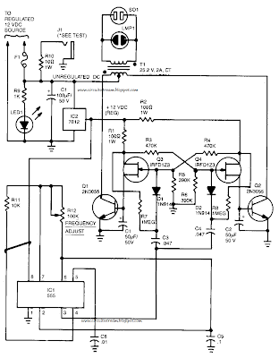
Hi Friends to we build a simple 60Hz Power Inverter Circuit Diagram.In the 60Hz Power Inverter Circuit Diagram Capacitor C5 and potentiometer R12 determine the frequency of the output signal at pin 3 of IC1, the 555 oscillator. The output signal is differentiated by C3 and C4 before it`s input to the base of power transistors Q1 and Q2 via diodes D1 and D2, respectively. 

The signal from !C1 is adjusted to 120Hz, because the flip-flop formed by transistors Q3 and Q4.divides the frequency by 2.When Q3 is on, the base of Q1 is connected via R1 to the regulated 12-V supply. Then, when the flipflop changes states, Q4 is turned on and the base of Q2 connected to the 12-V supply through R2. The 100 mA base current allowsQ1 and Q2 to alternately conduct through their respective halves to the transformer`s secondary winding. 

 60Hz Power Inverter Circuit Diagram

60Hz Power Inverter Circuit Diagram


To eliminate switching transients caused by the rapid switching of Q3 and Q4, capacitors C1 and C2 filter the inputs to the base of Q1 and Q2 respectively. Power for the unit comes from an automobile`s 12V system or from a storage battery. The power is regulated by IC2, a 7812 regulator. LED1, connected across the 12-V input, can be used to indicate whether power is being fed to the circuit. The neon pilot lamp, LMP1, shows a presence or absence of output power.


[Continue reading...]

Thursday, December 26, 2013

Single Chip Theremin Circuit Diagram

- 0 comments
This schematic diagram show a single chip Theremin circuit.  Theremin is an electronic music instrument which sense hand movement to control the tones/frequency.  This Theremin circuit uses two separate Colpitts LC oscillators to produce a beat frequency. 

The frequencies of  two Colpitts LC oscillators are mixed and then rectified. This rectification  demodulate the mixed signal to get the beat frequency which is in audible range. This beat frequency or difference is the real  Theremin’s output. The oscillator is operated at high frequency (inaudible) to get wide audible frequency range of beat frequency when two oscillator output is mixed.  This circuit uses a 4011 quad gate to construct the high frequency oscillator operating at 250kHz. Here is the schematic diagram of the circuit.

Single Chip Theremin Circuit Diagram

Single Chip Theremin Circuit Diagram

The metal probe that is used to sense your  hand produces only small frequency shift in term of percentage of original frequency, that’s why we need to derive the beat frequency to get wide audible frequency range as the result of  high frequency shifting. The IC2, an LM741 is used to amplify the mixed signal before rectification. 

The D1 will  rectify the mixed signal to detect the audio (the beat frequency).  This audio signal is then filtered by an adjustable bandpass filter IC3. The further audio amplification before power amplifier IC5  is done by IC4. The metal toilet-tank float  is used for the hand probe since is has better sensitivity than a simple wire antenna, but any conductive material will work.
[Continue reading...]

Simple Active ir Motion Detector Circuit Diagram

- 0 comments
To explore how different motion detectors operate.To successfully build and test an ambient-light-ignoring active IR motion detector.

Background
 There are a wide variety of motion detectors available currently. To allow a better understanding of motion detectors,the following section provides a detailed description of a few different types.

Ultrasonic Motion Detectors
Ultrasonic transducers can be used to detect motion in an area where there are not supposed to be any moving objects.This type of motion detector is most commonly used in burglar alarm systems since they are very effective in this application.


 Figure 1 shows the operation of an ultrasonic motiondetector. There are tw1o transducers: one emits an ultrasonicwave and the other picks up reflections from the differentobjects in the area. The reflected waves arrive at the receiverin constant phase if none of the objects in the area are moving.If something moves, the received signal is shifted in phase. 

A phase comparator detects the shifted phase and sends a triggering pulse to the alarm.Ultrasonic motion detectors have certain advantages and disadvantages when compared with other types of motion detectors. The main advantages is that they are very sensitive and extremely fast acting. However, the largest problem with this type of motion detector is that it sometimes responds to normal environmental vibration that can be caused by a passing car or a plane overhead. Some types of motion detectors use infrared sensors to avoid this problem, but even these detectors have some problems.

 Passive Infrared Motion DetectorIn passive infrared motion detectors, a sensorcontaining an infrared-sensitive phototransistor is placed in thearea to be protected. Circuitry within the sensor detects theinfrared radiation emitted by the intruder`s body and triggersthe alarm. 

The problem with using this type of detector is that it can be falsely triggered by warm air movement or other disturbances that can alter the infrared radiation levels in an area. In order to prevent this problem, newer systems use tw1oinfrared sensors which monitor different zones within a protected area. Logic within system triggers the alarm only when the tw1o zones are activated in sequence, as would occur if a person walked through the protected area.

Active Infrared Motion Detector


Figure 2 shows the operation of an active infrared motion detector. In the active system each sensor consists oftw1o housings. One housing contains an infrared-emitting diode and an infrared-sensitive photo transistor. The other housing contains an infrared reflector.When positioned in front of an entrance to a protected area, the tw1o housings establish an invisible beam. A person entering the area interrupts the beam causing an alarm to be triggered. An active motion detector is much more reliable than a passive one, but it requires careful alignment when it is installed. The detector can be falsely triggered if one of the housings moves slightly and causes a discontinuous beam.

Project
 For our project, we decided to construct an activeinfrared motion detector. Originally, we wanted to build both anIR and an ultrasonic detector, but we decided that an ultrasonicdetector would require too much time for a three week project.However, we also decided that just building an IR motiondetector would probably be a trivial exercise. 

So, we decided to expand on the concept by building an ambient light ignoring motion detector.This type of motion detector uses the same basic concept as the active infrared motion detector. An interruption in a 5kHz modulated pulsating beam that is transmitted by an infrared diode and received by an infrared transistor sets off the alarm. A schematic of this motion detector is given in Figure 3.

Simple Active ir Motion Detector  Circuit Diagram

 Figure 3. Ambient-Light-Ignoring Active Motion Detector

The circuit on the left is the transmitter circuit that establishes a 5 kHz modulated infrared beam. As you can see from the schematic of the receiver circuit, a resonance-handbarrow amplifier reduces the detector`s sensitivity to stray light. C1 and L1 in IC2A`s feedback loop cause the op amp to pass only those frequencies at or near the LED`s 5 kHz modulation rate. IC2B`s output increases when the received signal is sufficient to drop the negative voltage across C2 below the reference set by R2. The output of this circuit is then attached to some load resistance, which can be an alarm or, for demonstration purposes, an LED.
[Continue reading...]

1W BTL Audio Amplifier

- 0 comments
The TDA8581(T) from Philips Semiconductors is a 1-watt Bridge Tied Load (BTL) audio power amplifier capable of delivering 1 watt output power into an 8-Wload at THD (total harmonic distortion) of 10% and using a 5V power supply.

The schematic shown here combines the functional diagram of the TDA8551 with its typical application circuit. The gain of the amplifier can be set by the digital volume control input. At the highest volume setting, the gain is 20 dB. Using the MODE pin the device can be switched to one of three modes: standby (MODE level between Vp and Vp–0.5 V), muted (MODE level between 1 V and Vp–1.4 V) or normal (MODE level less than 0.5 V). The TDA8551 is protected by an internal thermal shutdown protection mechanism. The total voltage loss for both MOS transistors in the complementary output stage is less than 1 V.

1 Watt BTL Audio Amplifier Circuit diagram:

1 Watt BTL Audio Amplifier Circuit Diagram


Using a 5-V supply and an 8-W loudspeaker, an output power of 1 watt can be delivered. The volume control has an attenuation range of between 0 dB and 80 dB in 64 steps set by the 3-state level at the UP/DOWN pin: floating: volume remains unchanged; negative pulses: decrease volume; positive pulses: increase volume Each pulse at he Up/DOWN pin causes a change in gain of 80/64 = 1.25 dB (typical value).

When the supply voltage is first connected, the attenuator is set to 40 dB (low volume), so the gain of the total amplifier is then –20 dB. Some positive pulses have to be applied to the UP/DOWN pin to achieve listening volume. The graph shows the THD as a function of output power. The maximum quiescent current consumption of the amplifier is specified at 10 mA, to which should be added the current resulting from the output offset voltage divided by the load impedance.

Source : http://www.ecircuitslab.com/2011/05/1w-btl-audio-amplifier-circuit-diagram.html
[Continue reading...]

The self protection can avoid the happening of over voltage

- 0 comments
The self protection can avoid the happening of over voltage for cell phone jammer .
Domestic mobile Internet into the outbreak, followed by the huge market potential is attracting people of insight. With speeds faster and faster, more powerful mobile terminals, a number of new mobile Internet applications have emerged.
Here are some examples of the Internet do a better job abroad, you can share with you. This is a combination of cell phone location Foursquare is more characteristic, and it is a portable product, and its social, as is the interaction of social contact, and phone and are one to one, and it anytime, anywhere and people can connect together, so it is the location for a successful service. ShopSavvy is a class e-commerce applications, it is to phone all the available features are integrated in one, it is convenient to be able to scan some bar codes Camera, then this product is identified, because the phone is a social network, connect to the network can get more information, one can check information on the Internet, on the other hand it also combines a lot of location information, mobile devices have a joint position, it can to find you around the store price of this product What about, then marked on the map. The cooling fan is specially made for cell phone jammer .On the other hand, it is the users information to add into the evaluation, this product is the phones various functions applied to an extreme. Layar is a location-based services, is a mobile browser, according to the location of cell phone GPS to determine to determine the appropriate number of points of interest nearby, near the information presented in the information integration of these mobile phones. This radar can see through the inside of some nearby points of interest, points of interest and your small number of entities from the above point that out, and then click into the details later, such as the nearby McDonalds to see if there is no coupon, it information to coupons will be displayed, on the one hand a lot of information together and on the other hand is a one-stop, or even an end to end service, from initial inquiry to final a phone call, even after integration of e-commerce functions will in them. That is based on the user experience of mobile Internet, it is necessary the integration of multiple applications. Mobile application development is the need to tackle the key issues, we must find the real applications to meet user needs, large vendors have time to find a little place of concern, with a small adaptation to user needs the application to value. For example, read the industry chain for mobile phone operators can book through the publishing entities to develop games, shooting film, so as to gradually increase in the mobile phone industry chain read influence. In addition, the home market for China Mobile has strategic significance, should develop innovative end products, integrated information service platform to build the family, the family will be introduced to various types of services. Also, the development of mobile Internet for the digital entertainment industry provides opportunities for interactive entertainment market has great potential.
[Continue reading...]

Wednesday, December 25, 2013

Simple Wind battery Charger Circuit Diagram
- 0 comments
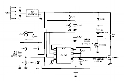
This is a Simple Wind battery Charger Circuit Diagram. The dc motor is used as a generator with the voltage output being proportional to its rpm. The LTC1042 monitors the voltage output and provides the following control functions. If generator voltage output is below 13.8 V, the control circuit is active and the Ni-Cad battery is charging through the LM334 current source. The lead acid battery is not being charged. 

If the generator voltage output is between 13.8 V and 15.1 V, the 12 V lead acid battery is being charged at about 1 amp/hour rate (limited by the power FET). If generator voltage exceeds 15.1 V (a condition caused by excessive wind speed or 12 V battery being fully charged) then a fixed load is connected limiting the generator rpm to prevent damage. This charger can be used as a remote source of power where wind energy is plentiful such as on sailboats or remote radio repeater sites. Unlike solar powered panels, this system will function in bad weather and at night.

Simple Wind battery Charger Circuit Diagram

Simple Wind battery Charger Circuit Diagram

[Continue reading...]

Ultrasonic Dog Whistle

- 0 comments
Its well known that many animals are particularly sensitive to high-frequency sounds that humans cant hear. Many commercial pest repellers based on this principle are available, most of them operating in the range of 30 to 50 kHz. My aim was, however, to design a slightly different and somewhat more powerful audio frequency/ultrasonic sound generator that could be used to train dogs. Just imagine the possibilities - you could make your pet think twice before barking again in the middle of the night or even subdue hostile dogs (and I guess burglars would love that!).

From what Ive read, dogs and other mammals of similar size behave much differently than insects. They tend to respond best to frequencies between 15 and 25 kHz and the older ones are less susceptible to higher tones. This means that an ordinary pest repeller wont work simply because dogs cant hear it. Therefore, I decided to construct a new circuit (based on the venerable 555, of course) with a variable pitch and a relatively loud 82 dB miniature piezo beeper.

The circuit is very simple and can be easily assembled in half an hour. Most of the components are not really critical, but you should keep in mind that other values will probably change the operating frequency. Potentiometer determines the pitch: higher resistance means lower frequency. Since different dogs react to different frequencies, youll probably have to experiment a bit to get the most out of this tiny circuit. The circuit is shown below:

Circuit diagram
Circuit Project: Ultrasonic Dog Whistle

Despite the simplicity of the circuit, there is one little thing. The 10nF (.01) capacitor is critical as it, too, determines the frequency. Most ceramic caps are highly unstable and 20% tolerance is not unusual at all. Higher capacitance means lower frequency and vice-versa. For proper alignment and adjustment, an oscilloscope would be necessary. Since I dont have one, I used Winscope. Although its limited to only 22 kHz, thats just enough to see how this circuit works.

There is no need to etch a PCB for this project, perf board will do. Test the circuit to see how it responds at different frequencies. A 4k7 potentiometer in conjunction with a 10nF (or slightly bigger) capacitor gives some 11 to 22kHz, which should do just fine. Install the circuit in a small plastic box and if you want to, you can add a LED pilot light. Power consumption is very small and a 9V battery should last a long time.

Possible further experimentation: Im working on an amplified version of the whistle to get a louder beep. All attempts so far havent been successful as high frequency performance tends to drop dramatically with the 555. Perhaps I could use a frequency doubler circuit - I just dont know and Ive run out of ideas. One other slightly more advanced project could be a simple "anti-bark" device with a sound-triggered (clap) switch that sets off the ultrasonic buzzer as soon as your dog starts to bark.
[Continue reading...]

Administrator has the highest administrative authority

- 0 comments
 The intelligent shielding system of phone jammer intelligent system for a unit is built.
System automatically before each run radio interface unit to connect the RF path calibration, system testing to ensure accuracy. Automated test software is the nerve center of the entire system, it can according to different types of test equipment and RF test instrumentation control switch, complete the testing process, test results and graphs of data saved to the SQLServer database and automatically generate reports. From the functional test automation software can be divided into four parts: system management, online testing, off-line test, view the report. Shown in Figure 3. Automated test software with rights management, into three groups: administrators, testers and visitors. Administrator has the highest administrative authority, to use all the features of the software; testers access times, in addition do not have administrative privileges, other privileges are available; visitors access the lowest, only off-line testing and reporting inquiry. Figure 4 shows the device under test automated testing process. Signals on the GSM, CDMA, DCS, PHS, and 3G bands can be stopped by phone jammer .
First, prompted by the tester to connect the device under test, fill out the necessary test information, and then the user needs to select the test project, either in accordance with the selection of all the test items can also be chosen based on some of the test items. Software testing process will be based on different test items automatically set switches and instrument parameters. After testing, the system prompts the user to save the test results, test results and some of the test pattern stored in the database. Saved to the database for test data, test can be queried at any time, and generate word-type test reports. The base station RF automated test system installed in a large test enclosure, the system run by high-performance workstations, centralized control, test software according to user requirements to complete standard test items for each base station.label model is correct and in line with company requirements; location is correct, no tilt, no more than 5 ° of tilt; phone labels should be in Chinese or symbols, abbreviations represent the following: manufacturer, model, without Commission approval of Certificate No. (CMII), CE mark and the IMEI number (GSM standard), or the corresponding number (other formats).Note 2: You can use room temperature with 5% ± 1% of the way instead of Nacl solution soak salt spray test. DOME with elastic stretch test measured the size of line drawings. endurance test machine with buttons, to exert a certain force (according to design requirements), press the speed of 40-60 beats / minute, press the button (with Dome) 10 million times, the test button after checking the appearance of non-cracking damage and functioning: Dome of the function is normal to pass.
[Continue reading...]

Panic Alarm

- 0 comments
Imagine the Panic situation in the Midnight when an intruder tries to break into the house. This Alarm will help you with its loud Police siren to abort the attempt of intrusion. With a single clap, the circuit generates the alarm for three minutes and then goes off. This is sufficient to catch the attention of neighbours.

The circuit is a sensitive Clap switch with timer action. IC1 is designed as a sensitive inverting amplifier to amplify the sound signals from the condenser mic. Variable resistor VR1 set the sensitivity of mic and resistor R1 and VR2 set the gain of the amplifier. If the sensitivity of mic and amplifier is suitably adjusted, the circuit can detect the sound from a distance of 5meters or more.

Circuit Project: Panic Alarm Circuit
Panic Alarm Circuit Diagram

When the mic detects clap sound, the ac signals pass through C1and IC1 amplifies the signal. This triggers T1 .When T1 conducts, the trigger pin of the Monostable Timer IC2 will be grounded and the timer triggers. With the given values of R5 and C2, output of IC2 remains high for three minutes. This high output provides power to the ROM IC UM3561.

It generates the Police Siren since its pin6 remains unconnected. Resistor R8 determines the frequency of oscillation of IC3.The siren signals are amplified by T2 and the alarm tone can be heard through the speaker. Zener diode ZD gives 3.1 volt regulated supply to IC3.
[Continue reading...]

Dual Regulated Power Supply

- 0 comments

In this circuit, the 7815 regulatates the positive supply, and the 7915 regulates the negative supply. The transformer should have a primary rating of 240/220 volts for europe, or 120 volts for North America.

Dual Regulated Power Supply Circuit diagram :

Dual Regulated Power Supply-Circuit Diagram

The centre tapped secondary coil should be rated about 18 volts at 1 amp or higher, allowing for losses in the regulator. An application for this type of circuit would be for a small regulated bench power supply.

[Continue reading...]

Tuesday, December 24, 2013

The list of wholesale cell phone jammer has been prepared

- 0 comments
The list of wholesale cell phone jammer has been prepared.
Active set, also known as the active set, and assigned to the mobile stations former frequency to the traffic channel corresponding to the guide. Not in the active set, but has enough strength that the frequency corresponding to the base station with the guide to the business channel can be successfully demodulated pilot collection. Chinas leading communications technology forum 8f "O.Z2t: U% d% G /]! S is not currently activated set and candidate set but it is possible to enter the candidate set of pilot collection in the current system, the CDMA frequency allocation under all possible pilot, in addition to containing frequency in the active set, candidate set and the adjacent pilot focused guide the pilot set to determine the list of messages and a list of Neighborhood Neighborhood Update the parameters PILOT_INC messages. The pilot system bias may is just PILOT_INC of an integer multiple of. The heavy current circuit also includes 220V power supply wire supplying power to cell phone jammer itself.The inspector is checking the content of acceptance standard of cell phone jammer system
The base station to mobile station to send the extended switching indication message EHDM (Extended Handoff Direction Message) or ordinary switch directions message GHDM (General Handoff the Direction Message). mscbsc Mobile Communications Forum has 300,000 communications professionals, more than 50 million copies of GSM/3G and information communication technology, the country O3) the mobile station the pilot included in the active set and switch to the base station to send a message of HCM (Handoff Completion the Message) . , It corresponds to the switch to remove the timer timer started when the pilot strength is lower than T_DROP. When the switch remove the overflow timer expires, the mobile station to the base station to send conduction band strength measurement message. Hold every cell phone and test the effective shielding radius of cell phone jammer from the near to the distant starting from cell phone jammer installation position.
Base station to mobile station to send EHDM or GHDM. Mobile station to the pilot moved to the candidate set, and switch to the base station sends a message of HCM. Pilot home to search for mobile communications, communications engineers, communications personnel, job recruitment, network optimization, traffic engineering, travel accommodation, communications companies blacklist. a variety of conductivity of the above, the base station frequency of collection, respectively, provides for the corresponding search window (PN code phase offset range), mobile search corresponding to the pilot all the available focus on the pilot multipath components in each window. Search window is the active set and candidate set SRCH_WIN_A to determine the search window of the neighbor set is determined by the SRCH_WIN_N SRCH_WIN_R provides for a residual set of search window. These three parameters are included in the paging channel to send the system parameters message. The inspector is checking the content of acceptance standard of cell phone jammer system.
[Continue reading...]

12 volt Cellar Drain Pump

- 0 comments
This circuit lets you control a pump, to keep the level of water in a cellar below a certain threshold, for example. Power  is supplied to the pump by a battery that is recharged auto matically when the AC power line voltage is present.

12-volt Cellar Drain Pump Circuit Diagram

12-volt Cellar Drain Pump-Circuit Diagram

lf the water  level  rises, the electrodes touch the liquid and a current begins to flow. The transistor then conducts and the pump runs. The pump stops when the water level has dropped sufficiently for the electrodes to no longer be in contact with it but not straight away, as the voltage on the transistor gate is maintained for a few seconds more by the 470 ytF capacitor. This makes it possible to ensure  the electrodes are completely clear of the water.

The battery is constantly tested by the comparator circuit around the T1071 lC.  lts output drives the  gate of the triac  in the transformer primary circuit via the optoisolator. The transformer secondary charges the battery via the rectifier,  using as little power as possible, and in this way keeps the battery at 13.2 V.


[Continue reading...]

Zener Diode Increase Regulator Output Circuit Diagram

- 0 comments
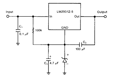
A zener diode in the ground lead of a fixed pnp regulator varies the voltage output of that device without a significant sacrifice in regulation. The technique also allows the regulator to operate with output voltages beyond its rated limit.

Zener Diode Increase Regulator Output Circuit Diagram

Zener Diode Increase Regulator Output Circuit Diagram
[Continue reading...]

TL594 12V DC Switch Mode Power Supply Rise

- 0 comments
Basic Of Switch Mode Power Supply
In recent years, the use of switch mode power supply (SMPS) has become more comon as more applications demand for greater power eficiency. It makes use of semiconductor (mostly MOSFET) fast switches to switch DC input that has been rectified at high frequency. The advantages of high frequency switching are that it reduces the size of inductor, capacitors & transformer used. Other advantages of switching power supply over linear power supply are :

1) High Efficiency (up to 90% and above for nice design).
2) Output can be higher than input.
3) Able to operate over a variety of input power supply.
4) Able to have over output.
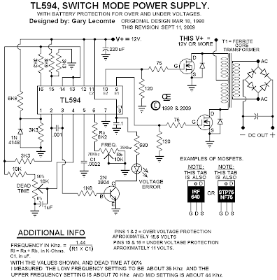
The setback of using SMPS compared to linear power supply is that it generates electrical noise which contributes to electromagnetic compatibility design issues & more part count.

Buck Converter SMPS
The SMPS circuit below from Power Integration makes use of LNK304 as its high frequency switch. Take note that this circuit is non isolated type which means that the output is not electrically isolated from the input & all testing ought to be completed using an isolation transformer to provide the AC line input to the board.

Make positive that you have electrical safety knowledge & experience before you embark on doing this project.

12V DC Switch Mode Power Supply Circuit Diagram


12V DC Switch Mode Power Supply Circuit Diagram


[Continue reading...]

Monday, December 23, 2013

Simple Precision full wave Rectifier Circuit Diagram

- 0 comments
The circuit provides accurate full wave rectification. The output impedance is low for both input polarities, and the errors are small at all signal levels. Note that the output will not sink heavy current, except a small amount through the 10K resistors. Therefore, the load applied should be referenced to ground or a negative voltage. Reversal of all diode polarities will reverse the polarity of the output

Since the outputs of the amplifiers must slew through two diode drops when the input polarity changes, 741 type devices give 5% distortion at about 300 Hz.


Precision full wave Rectifier Circuit Diagram

 Sourced By: http://circuitsstream.blogspot.com/2013/07/precision-full-wave-rectifier-circuit.html
[Continue reading...]

Four in One Burglar Alarm

- 0 comments
In this circuit, the alarm will be switched on under the following four different conditions: 1. When light falls on LDR1 (at the entry to the premises). 2. When light falling on LDR2 is obstructed. 3. When door switches are opened or a wire is broken. 4. When a handle is touched. The light dependent resistor LDR1 should be placed in darkness near the door lock or handle etc. If an intruder flashes his torch, its light will fall on LDR1, reducing the voltage drop across it and so also the voltage applied to trigger 1 (pin 6) of IC1. Thus transistor T2 will get forward biased and relay RL1 energise and operate the alarm. 

Sensitivity of LDR1 can be adjusted by varying preset VR1. LDR2 may be placed on one side of a corridor such that the beam of light from a light source always falls on it. When an intruder passes through the corridor, his shadow falls on LDR2. As a result voltage drop across LDR2 increases and pin 8 of IC1 goes low while output pin 9 of IC1 goes high. Transistor T2 gets switched on and the relay operates to set the alarm.

Four-in-One Burglar Alarm Circuit Diagram
Four-in-One Burglar-Alarm-Circuit-Diagram


The sensitivity of LDR2 can be adjusted by varying potentiometer VR2. A long but very thin wire may be connected between the points A and B or C and D across a window or a door. This long wire may even be used to lock or tie something. If anyone cuts or breaks this wire, the alarm will be switched on as pin 8 or 6 will go low. In place of the wire between points A and B or C and D door switches can be connected. These switches should be fixed on the door in such a way that when the door is closed the switch gets closed and when the door is open the switch remains open. If the switches or wire, are not used between these points, the points should be shorted. With the help of a wire, connect the touch point (P) with the handle of a door or some other suitable object made of conducting material. When one touches this handle or the other connected object, pin 6 of IC1 goes ‘low’.

So the alarm and the relay gets switched on. Remember that the object connected to this touch point should be well insulated from ground. For good touch action, potentiometer VR3 should be properly adjusted. If potentiometer VR3 tapping is held more towards ground, the alarm will get switched on even without touching. In such a situation, the tapping should be raised. But the tapping point should not be raised too much as the touch action would then vanish. When you vary potentiometer VR1, re-adjust the sensitivity of the touch point with the help of potentiometer VR3 properly. If the alarm has a voltage rating of other than 6V (more than 6V), or if it draws a high current (more than 150 mA), connect it through the relay points as shown by the dotted lines. As a burglar alarm, battery backup is necessary for this circuit. Note: Electric sparking in the vicinity of this circuit may cause false triggering of the circuit. To avoid this adjust potentiometer VR3 properly.

Source : http://www.ecircuitslab.com/2012/01/four-in-one-burglar-alarm.html
[Continue reading...]

Automatic Night Lamp with Morning Alarm

- 0 comments
This circuit automatically turns on a night lamp when bedroom light is switched off. The lamp remains ‘on’ until the light sensor senses daylight in the morning. A super-bright white LED is used as the night lamp. It gives bright and cool light in the room. When the sensor detects the daylight in the morning, a melodious morning alarm sounds. The circuit is powered from a standard 0-9V transformer. Diodes D1 through D4 rectify the AC voltage and the resulting DC voltage is smoothed by C1. Regulator IC 7806 gives regulated 6V DC to the circuit. A battery backup is provided to power the circuit when mains fails. When mains supply is available, the 9V rechargeable battery charges via diode D5 and resistor R1 with a reasonably constant current. In the event of mains failure, the battery automatically takes up the load without any delay. Diode D5 prevents the battery from discharging backwards following the mains failure and diode D6 provides current path from the battery.

Automatic Night Lamp with Morning Alarm Circuit Diagram

Automatic Night Lamp with Morning Alarm-Circuit-Diagram

The circuit utilises light-dependant resistors (LDRs) for sensing darkness and light in the room. The resistance of LDR is very high in darkness, which reduces to minimum when LDR is fully illuminated. LDR1 detects darkness, while LDR2 detects light in the morning. The circuit is designed around the popular timer IC NE555 (IC2), which is configured as a monostable. IC2 is activated by a low pulse applied to its trigger pin 2. Once triggered, output pin 3 of IC2 goes high and remains in that position until IC2 is triggered again at its pin 2. When LDR1 is illuminated with ambient light in the room, its resistance remains low, which keeps trigger pin 2 of IC2 at a positive potential. As a result, output pin 3 of IC2 goes low and the white LED remains off. As the illumination of LDR1’s sensitive window reduces, the resistance of the device increases.

In total darkness, the specified LDR has a resistance in excess of 280 kilo-ohms. When the resistance of LDR1 increases, a short pulse is applied to trigger pin 2 of IC2 via resistor R2 (150 kilo-ohms). This activates the monostable and its output goes high, causing the white LED to glow. Low-value capacitor C2 maintains the monostable for continuous operation, eliminating the timer effect. By increasing the value of C2, the ‘on’ time of the white LED can be adjusted to a predetermined time. LDR2 and associated components generate the morning alarm at dawn. LDR2 detects the ambient light in the room at sunrise and its resistance gradually falls and transistor T1 starts conducting. When T1 conducts, melody-generator IC UM66 (IC3) gets supply voltage from the emitter of T1 and it starts producing the melody. The musical tone generated by IC3 is standard 0-9V transformer. Diodes D1 through D4 rectify the AC voltage and the resulting DC voltage is smoothed by C1. Regulator IC 7806 gives regulated 6V DC to the circuit.
A battery backup is provided to power the circuit when mains fails. When mains supply is available, the 9V rechargeable battery charges via diode D5 and resistor R1 with a reasonably constant current. In the event of mains failure, the battery automatically takes up the load without any delay. Diode D5 prevents the battery from discharging backwards following the mains failure and diode D6 provides current path from the battery.
The circuit utilises light-dependant resistors (LDRs) for sensing darkness and light in the room. The resistance of LDR is very high in darkness, which reduces to minimum when LDR is fully illuminated. LDR1 detects darkness, while LDR2 detects light in the morning. The circuit is designed around the popular timer IC NE555 (IC2), which is configured as a monostable. IC2 is activated by a low pulse applied to its trigger pin 2. Once triggered, output pin 3 of IC2 goeshigh and remains in that position until IC2 is triggered again at its pin 2. When LDR1 is illuminated with ambient light in the room, its resistance remains low, which keeps trigger pin 2 of IC2 at a positive potential. As a result, output pin 3 of IC2 goes low and the white LED remains off. As the illumination of LDR1’s sensitive window reduces, the resistance of the device increases.

In total darkness, the specified LDR has a resistance in excess of 280 kilo-ohms. When the resistance of LDR1 increases, a short pulse is applied to trigger pin 2 of IC2 via resistor R2 (150 kilo-ohms). This activates the monostable and its output goes high, causing the white LED to glow. Low-value capacitor C2 maintains the monostable for continuous operation, eliminating the timer effect. By increasing the value of C2, the ‘on’ time of the white LED can be adjusted to a predetermined time. LDR2 and associated components generate the morning alarm at dawn. LDR2 detects the ambient light in the room at sunrise and its resistance gradually falls and transistor T1 starts conducting. When T1 conducts, melody-generator IC UM66 (IC3) gets supply voltage from the emitter of T1 and it starts producing the melody. The musical tone generated by IC3 is amplified by single-transistor amplifier T2. Resistor R7 limits the current to IC3 is amplified by single-transistor amplifier T2. Resistor R7 limits the current to IC3 and zener diode ZD limits the voltage to a safer level of 3.3 volts.

The circuit can be easily assembled on a general-purpose PCB. Enclose it in a good-quality plastic case with provisions for LDR and LED. Use a reflective holder for white LED to get a spotlight effect for reading. Place LDRs away from the white LED, preferably on the backside of the case, to avoid unnecessary illumination. The speaker should be small so as to make the gadget compact.

Source:   http://www.ecircuitslab.com/2012/02/automatic-night-lamp-with-morning-alarm.html
[Continue reading...]

IR Beam Breaker Schematics

- 0 comments

This is an Infrared beam breaking alarm ideal to use in entry or passages.It is based on the working of the popular IR sensor Module TSOP 1738 which senses 38 kHz Infrared pulses from the IR LED of the transmitter. Range of the circuit is about 5 meters if the transmitter and receiver are properly aligned TSOP 1738 IR sensor module responds to only 38kHz pulsed infrared rays.

Circuit diagram :

 IR-beam-breaker-Circuit Diagram

IR Beam Breaker Schematics Circuit Diagram

It will not sense continuous IR ray from the IR LED.So a transmitter circuit(as one in TV remote handset) based on 555 IC is required. Any standard transmitter circuit based on 555 IC can be used. But its output should be 38kHz exactly.TSOP 1738 gives 5 volt output and 5mA current in the off position. That is when IR rays are not available.Its output is current sinking so that when it receives 38kHz IR rays, output becomes zero.Pin 2 of the module should get a supply voltage between 4.5 to 6 volts.Higher voltage above 6 volts will destroy the device. The module is generally immune to ambient light, but may responds to sources of noice such as electronic ballasts.

Out put from the IR module is given to the inverting input of IC1. LM311 is a precision voltage comparator . It looks like the common Op Amps like LM741, CA3130,CA 3140,TL071 etc.But its pin connections and output are different from other Op Amps.

Pin 2 Non inverting

Pin3 Inverting

Pin 1 Ground

Pin8 Vcc

Pin7 Current sinking Output

IR-beam-breaker- LM-311

The non inverting input of IC1 is connected to a potential divider comprising R1 and R2. When the IR sensor gets IR pulses from the transmitter, output of IC1 remains high. When the IR beam breaks, output from the sensor becomes high which triggers IC1. It then sinks current to activate buzzer and LED.

[Continue reading...]

Safety Guard

- 0 comments
Simple unit, Protects home appliances from voltage spikes

Protect your home appliances from voltage spikes with this simple time delay circuit. Whenever power to the appliances is switched on or resumes after mains failure, the oscillator starts oscillating and D5 blinks. This continues for three minutes. After that, Q14 output of IC CD4060 goes high to trigger the gate of the SCR through D4. At this moment, the voltage is available at the cathode of the SCR, which energizes the relay coil to activate the appliance and D6 glows. Switch SW1 is used for quick start without waiting for delay.

Safety Guard Circuit Diagram

Safety Guard Circuit Diagram

Parts Description
R1 1M
R2 470R
R3 820R
R4 56K
R5 470R
R6 1K
R7 10K
C1 1kuF-25V
C2 100nF-63V
C3 0.02uF-63V
C4 10uF-25V
C5 10uF-25V
D1 1N4007
D2 1N4007
D3 1N4007
D4 1N4148
D5 Red LEDs
D6 Red LEDs
RL1 12V Relay
IC1 AN7809
IC2 CD4060
SW1 Switch
T1 24V-AC Centre Tapped Transformer

Circuit Operation:

At the heart of the circuit is IC CD4060, which consists of two inverter gates for clock generation and a 14-bit binary ripple counter. Here the clock oscillations are governed by resistor R1 and capacitor C1. In this circuit, only two outputs of the IC (Q5 and Q14) have been used. Q5 is connected to an LED (D5) and Q14 is used to trigger the gate of the SCR through D4 as well as reset the counter. The anode of the SCR is connected to +9V and the cathode is connected to the relay coil. The other pin of the relay coil is connected to the negative supply, while its contacts are used for switching on the appliances.

Source : http://www.ecircuitslab.com/2011/05/safety-guard.html


[Continue reading...]

Sunday, December 22, 2013

9V Automatic Battery NiCd Charger

- 0 comments
This automatic NiCd charger for 9V NiCd batteries is using 555 timer properties and is very easy to build. Why is an automatic 9 volts NiCd battery charger? Because you can leave the battery for charging as much as you like: it will be always completely charged and ready for use when is needed. It wont be overcharged and it will not discharge.

9V Automatic Battery NiCd Charger Circuit Diagram :

nicd-charger-circuit-diagram

With the values presented in the circuit diagram, the battery charger NiCd circuit is suitable for 6V and 9V batteries. 9 volt types with 6 and 7 cells are charging with 20mA; P1 must be adjusted so that the NiCd charger disconnects after 14 hours. Window inferior level is set at 1V below this value with P2. 5V battery type with 4 or 5 cells are charged at 55mA. Again, with P1 adjust the NiCd charger circuit so it disconnects after 14 hours. Window inferior level must be set at 0.8V below this value.

Source: http://www.ecircuitslab.com/2012/08/9v-automatic-battery-nicd-charger.html

[Continue reading...]

Build a Stand by Power Circuit Diagram for Non Volatile Cmos Rams

- 0 comments
This is  a simple Stand by Power Circuit diagram for Non Volatile Cmos Rams. To prevent loss of data when a CMOS RAM is switched from normal operation (Vcc = 5 volts) to stand-by mode (Vcc = VBAT) it must be ensured that the CS pin goes near the Vcc rail at all times. 

Ac coupling to the chip select is made through capacitor C, breaking the dc current path between Vqq (and hence VBAT) and the decoder output. So, whatever the impedance state of the decoder in power down, the battery will provide current only for the RAM, low enough to keep the voltage at CS near to V^.

Power Circuit Diagram

Build a Stand by Power Circuit Diagram for Non Volatile Cmos Rams Circuit diagram

[Continue reading...]

Running Message Display Schematics Circuit

- 0 comments

Light emitting diodes are advantageous due to their smaller size, low current consumption and catchy colours they emit. Here is a running message display circuit wherein the letters formed by LED arrangement light up progressively. Once all the letters of the message have been lit up, the circuit gets reset. The circuit is built around Johnson decade counter CD4017BC (IC2). One of the IC CD4017BE’s features is its provision of ten fully decoded outputs, making the IC ideal for use in a whole range of sequencing operations.In the circuit only one of the outputs remains high and the other outputs switch to high state successively on the arrival of each clock pulse.

Circuit diagram :

Running Message Display -Circuit diagram

Running Message Display Circuit Diagram

The timer NE555 (IC1) is wired as a 1Hz astable multivibrator which clocks the IC2 for sequencing operations. On reset, output pin 3 goes high and drives transistor T7 to ‘on’ state. The output of transistor T7 is connected to letter ‘W’ of the LED word array (all LEDs of letter array are connected in parallel) and thus letter ‘W’ is illuminated. On arrival of first clock pulse, pin 3 goes low and pin 2 goes high. Transistor T6 conducts and letter ‘E’ lights up. The preceding letter ‘W’ also remains lighted because of forward biasing of transistor T7 via diode D21. In a similar fashion, on the arrival of each successive pulse, the other letters of the display are also illuminated and finally the complete word becomes visible. On the following clock pulse, pin 6 goes to logic 1 and resets the circuit, and the sequence repeats itself. The frequency of sequencing operations is controlled with the help of potmeter VR1.


The display can be fixed on a veroboard of suitable size and connected to ground of a common supply (of 6V to 9V) while the anodes of LEDs are to be connected to emitters of transistors T1 through T7 as shown in the circuit. The above circuit is very versatile and can be wired with a large number of LEDs to make an LED fashion jewellery of any design. With two circuits connected in a similar fashion, multiplexing of LEDs can be done to give a moving display effect

[Continue reading...]
 
Copyright © 2012. Fast Diagrams - Posts · Comments
Powered by Blogger