Showing posts with label level. Show all posts

Monday, November 17, 2014

Hot Water Level Indicator

- 0 comments

Notes:
Save fuel bills and the economy of the planet with this circuit. SW1 is a normally open press button switch which allows you to view the level of hot water in a hot water tank. When pressed the voltage difference at the junction of the thermistor and preset is compared to the fixed voltage on the op-amps non-inverting input. Depending on the heat of the water in the tank, the thermistors resistance will toggle the op-amp output to swing to almost full voltage supply and light the appropriate LED.

Construction:
Masking tape was used to stick the bead thermistors to the tank. Wires were soldered and insulated at the thermistors ends. A plastic box was used to house the circuit. Battery life will probably be 4 to 5 years depending on how often you use the push switch, SW1.

Sensor Placement:
Thermistors NTC1-4 should be spread evenly over the height of the tank. I placed NTC1 roughly 4 inches from the top of my tank and the others were spaced evenly across the height of the hot water tank. As hot water rises the lowest sensor indicates the fullest height of hot water and should be about 8 to 10 inches from the bottom of the tank.

Calibration:
With a full tank of hot water adjust P1-4 so that all LEDs are lit. As hot water rises, the sensor at the bottom of the tank will be the maximum level of hot water. "Hot" can be translated as 50C to 80C the presets P1-4 allow adjustment of this range.

Parts:

I have used a quad version of the LM324 but any quad opamp can be used or even four single op-amps.
R2-R5 I used 330ohm resistors, but value is not critical. Lower values give brighter LED output.
NTC1-4 The thermistors maximum resistance must roughly equal the resistance of the fixed resistor and preset. As negative temparature coefficient (NTC) thermistors are used, then their resistance decreases for increases in temperature. I used a thermistor from the Maplin Catalogue. Cold resistance was around 300K, hot resistance 15k. Alternative thermistors may be used with different resistance ranges, but the presets P1 to P4 must also be changed as well.

R7-10 series resistance, only required if your thermistors resistance is several ohms at the hottest temperature.
P1 - P4 Chosen to match the resistance of the thermistor when cold.
R1 & R6. These resistors are equal and bias the op-amp inverting input to half the supply voltage. I used 100k.
[Continue reading...]

Wednesday, November 5, 2014

Petrol Diesel Level Sensor

- 0 comments
This sensor is particularly suitable for use in small spaces, such as the petrol tank of a  motorbike. It has the advantage of not having any moving parts, unlike a conventional sensor with a float and float arm that make it difficult to fit in a tank.

The sensor circuit is made from standard, inexpensive components and can be put together for little money.

Petrol/Diesel Level Sensor Circuit diagram :

Sensor-Circuit


The operating principle is  based on  measuring  the forward volt-ages of two identical diodes (check this  first by measuring  them).  The forward voltage of a diode decreases with increasing junction temperature. lf a resistor is placed close to one of the two diodes, it will be heated slightly if it extends above the surface of the  petrol. For best results,the other diode (used for reference) should be located at the same level. lf the diodes are covered by the petrol in the tank, the heating resistor will not have any effect because it will be cooled by the petrol. An opamp compares the voltage across the two diodes, with a slightly smaller current passing through the reference diode. 

When the petrol level drops, the output of the opamp goes high and the output transistor switches on. This causes a sense resistor to be connected in parallel with the sensor output. Several sensor circuits can be used together, each with its own switched sense resistor connected in parallel with the output, and the resulting output  signal can be used to drive a meter or the like.

Using this approach, the author built a petrol tank sensors trip tank consisting of five PCBs, each fitted with two sensor circuits. With this sensor strip installed at an angle in the tank, a resolution of approximately 1.5 litre per sensor is possible. Many tanks have an electrical fitting near the bottom for connection to a lamp on the instrument panel that indicates the reserve level. The sensor strip can be used in its place. You will have to experiment a bit with the values of the sense resistors, but do not use values lower than around100 O. It is also important to fit the diodes and heater resistor in a little tube with a small opening at the bottom so that splashing petrol does not cool the heater resistor, since this would result in false readings.

The circuit should be powered from a regulated supply voltage of 5 to 6 V to prevent the heating resistors from becoming too hot. After testing everything to be sure that it works properly, its a good idea to coat the circuit board with epoxy glue to provide better protection against the petrol.

Tip: you can use the well-known 1M3914 to build a LED display with ten LEDs, which can serve as a level indicator. Several examples of suitable circuits can be found in back issues of Elektor.

Note: this sensor circuit is not suitable for use in conductive liquids.
[Continue reading...]

Wednesday, April 10, 2013

LM3914 battery level indicator

- 0 comments
LM3914 battery level indicator
Battery level indicator circuit is a circuit that is used to measure the battery voltage / battery. The main components of the battery level indicator circuit is an LM3914 IC. LM 3914 on Circuit battery level indicator is a monolithic IC that detects an analog voltage. And drive the 10 LEDs that produce a linear analog display on a given input voltage.

IC LM3914 is easy to get in the market and not expensive. IC LM3914 battery level indicator on the circuit is often encountered in a series of peak indicator audio signals in analog audio equipment. Battery level indicator circuit consists of IC LM3914, 10 pieces of LED, and a few resistors. The scheme of  battery level indicator can be seen below.

LM3914 battery level indicator

In the circuit of the battery level indicator on the supply circuit voltage taken from the battery / batteries through a switch. Didesaimn this circuit will only display the battery level when the switch is pressed. This is intended to save the battery voltage itself.
[Continue reading...]

Tuesday, April 9, 2013

Measure your stress level – Tension meter

- 0 comments
If you, like so many other people in this day and age, arrive home from work stressed out and with the problems of the day still lingering,this simple little instrument will go a long way to relieving nervous tension.
Of the various types of feedback devices, probably the best approach for the amateur experimenter is the Galvanograph, better known as the Galvanic Skin Response Monitor. The instrument described here relies for its operation on changes in skin resistance in sympathy with changes in emotional state. An increase in tension level reduces skin resistance and, conversely, a decrease in tension is accompanied by an increase in skin resistance.
The correlation between emotional stress and skin resistance is still not fully understood. What is known, though, is that minute changes in the permeability of the skin produce corresponding voltage variations across two electrode pads attached to two fingers on the same hand.

Measure tension meter


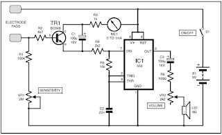
Tension Monitor meter circuit

These signal fluctuations are amplified and fed to an oscillator to produce an audible tone. A decrease in pitch therefore signifies a decrease in tension, and vice-versa. A visual indicator in the form of a panel meter also aids the user in monitoring tension levels. The monitor is quite sensitive to fluctuations. During use, a sudden moment of stress, even a deep sigh, will increase the pitch and cause a shift of the meter needle. Circuit Details In the circuit diagram of Fig.1, IC1 is configured as an astable multivibrator to drive an 8-ohm miniature speaker LS1 via capacitor C3, resistor R6 and volume control potentiometer VR2. The latter allows users to set a desired level and avoid it becoming a distraction.
Whereas the trigger input of IC1 is normally connected to the positive rail via a resistor in a conventional 555 oscillator, here it is connected via resistor R4 to the emitter of transistor TR1. The base of TR1 is connected between one electrode pad and the voltage divider formed by potentiometer VR1 and resistor R1. It will be seen that with the pads fitted to the fingers, the tone level will be dependent on the setting of VR1 and skin resistance. Resistor R2 in the transistor base is necessary should the pads be accidentally touched together. A 1mA meter is fitted in the collector line, along with R3, as a visual indicator. Although not essential or intended to measure current levels, it does help to emphasize fluctuations in emotional level.
The design of the pads is not critical. For the prototype, stripboard was used. The tracks were wired together at one end and connected to a 30cm length of twin lighting flex. The pads were then glued to Velcro straps. When the unit is first switched on, a highpitched tone should be heard, rapidly diminishing and ceasing. Turn the Sensitivity control VR1 to the minimum setting. Attach the electrodes to the fleshy pads of the first two fingers on the less-dominant hand with the Velcro straps, firmly but not tight. Rest the hand comfortably and keep it reasonably still, allowing half a minute for the pads to “bond”. Normally, at the minimum setting, the oscillator will hardly tick over, unless the user is in a high state of anxiety. Keep in mind that any form of stimulant, and that includes tea, coffee, alcohol and cigarettes, will reduce one’s capacity to relax. Rotate the control until a medium pitched tone is obtained and apply your relaxation technique. The monitor does not teach any method of meditation or relaxation; it only monitors the effectiveness of the technique applied. The tone should slowly diminish, with fluctuations as unconscious thoughts flit across the mind.When the sound ceases altogether, repeat the above procedure by increasing VR1. Twenty minutes is considered by therapists to be an adequate relaxation session.
[Continue reading...]
 
Copyright © 2012. Fast Diagrams - Posts · Comments
Powered by Blogger