Showing posts with label battery. Show all posts

Thursday, October 30, 2014

using L200 Battery Charger Circuit Diagram

- 0 comments
This is a simple circuit using L200 Battery Charger Circuit Diagram. A very simple battery charger circuit having reverse polarity indication is shown here.The circuit is based on IC L200 . L200 is a five pin variable voltage voltage regulator IC. The charging circuit can be fed by the DC voltage from a bridge rectifier or center tapped rectifier.Here the IC L200 keeps the charging voltage constant.The charging current is controlled by the parallel combination of the resistors R2 & R3.The POT P1 can be used to adjust the charging current.

 Battery charger circuit using L200 With Parts list


This circuit is designed to charge a 12 V lead acid battery.The transistor t1,diode D3 and LED are used to make a battery reverse indicator.In case the battery is connected in reverse polarity ,the reverse polarity indicator red LED D5 glows.When the charging process is going on the battery charging indicator green LED D4 glows.

Notes.
The circuit can be assembled on a good quality PCB or common board.
The values of R2 & R3 can be obtained from the equation,
(R2//R3) =( V5-2)/(Io).
Where V5 is  the charging voltage (voltage at pin 5) and Io is the charging current.
The POT R8 can be used for fine adjustments of charging current.
If battery is connected in reverse polarity the RED LED will glow.
When the  charging is going on the GREEN LED will glow.
The rectified input voltage to the charger can be 18V.


Sourced By: Circuitsstream
[Continue reading...]

Wednesday, October 29, 2014

Low Cost Universal Battery Charger Schematic

- 0 comments
This is the circuit diagram of a low cost universal charger for NiCD - NiMH batteries. This circuit is Ideal for car use. It has ability to transform a mains adapter in to a charger . This one can be used to charge cellular phone, toys, portables, video batteries, MP3 players, ... and has selectable charge current. An LED is located in circuit to indicate charging. Can be built on a general purpose PCB or a veroboard. I hope you really like it.

Picture of the circuit:

 a_low_cost_universal_charger 
 A Low Cost Universal Charger Circuit Schematic
Circuit diagram:
a_low_cost_universal_charger_circuit_diagram_for_nicd
A Low Cost Universal Charger Circuit Diagram


Parts:
R1 = 120R-0...5W
R2 = See Diagram
C1 = 220uF-35V
D1 = 1N4007
D2 = 3mm. LED
Q1 = BD135
J1 = DC Input Socket
Specifications:
  • Ideal for in car use.
  • LED charge indication.
  • Selectable charge current.
  • Charges Ni Cd or NiMH batteries.
  • Transforms a mains adapter into a charger.
  • Charge cellular phone, toys, portables, video batteries …
Features:
  • LED function indication.
  • Power supply polarity protected.
  • Supply current: same as charge current.
  • Supply voltage: from 6.5VDC to 21VDC (depending on used battery)
  • Charge current (±20%): 50mA, 100mA, 200mA, 300mA, 400mA. (selectable)
Determining the supply voltage:
This table indicates the minimum and maximum voltages to supply the charger. See supply voltage selection chart below.
Example:
To charge a 6V battery a minimum supply voltage of 12V is needed, the maximum voltage is then 15V.
Voltage selection:

supply_voltages_selection_chart_for_
Voltage Selection Chart For Low Cost Universal Battery Charger

Determining the charge current:
Before building the circuit, you must determinate how much current will be used to charge the battery or battery pack. It is advisable to charge the battery with a current that is 10 times smaller then the battery capacity, and to charge it for about 15 hours. If you double the charge current , then you can charge the battery in half the time. Charge current selection chart is located in diagram.

Example:
A battery pack of 6V / 1000mAh can be charged with 100mA during 15 hours. If you want to charge faster, then a charge current of 200mA can be used for about 7 hours.
Caution:
The higher charge current, the more critical the charge time must be checked. When faster charging is used, it is advisable to discharge the battery completely before charging. Using a charge current of 1/10 of the capacity will expand the lifetime of the battery. The charge time can easily be doubled without damaging the battery.
Note:
  • Mount the transistor together with the heatsink on the PCB, bend the leads as necessary. Take care that the metal back of the transistor touches the heatsink. Check that the leads of the transistor do not touch the heatsink.
[Continue reading...]

Wednesday, October 8, 2014

12v battery charger using transistors circuit

- 0 comments

A very simple 12v battery charger circuit can be designed using a TIP3055 power transistor to limit the current to the battery by turning off when the battery voltage reaches approx 14v or if the current rises above 2 amp.

This battery charger electronic circuit is very simple and require few external electronic parts . Signal to turn off the TIP3055 transistor comes from two other transistors , the BC557 and BC 547. Firstly, the circuit turns on fully via the BD139 and TIP3055. The BC557 and BC 547 do not come into operation at the moment.
As the battery voltage rises, the voltage divider made up of the 1k8 and 39k creates a 0.65v between base and emitter of the BC557 and it starts to turn on at approx 14v.
The input voltage required by this charger electronic circuit project must be around 15 volts DC.

12v

[Continue reading...]

Sunday, September 21, 2014

Dual Mode Battery Charger Circuit

- 0 comments

There are two main types of battery charger – constant voltage and constant current. Both have their advantages and disavantages. For constant voltage, the battery cannot be overcharged but the charging rate is slow. Constant current mode can charge batteries more swiftly but there is the danger of overcharging them.

The dual mode battery charger circuit featured here was designed to combine both modes, but without their disadvantages, for use with a 6V sealed lead-acid battery. The main players of the circuit are voltage regulator IC1, which is used for constant current mode, and precision adjustable shunt regulator IC2, which is used for constant voltage mode.

In constant current mode, resistor R4 sets the current at 370mA, according to the equation:
R4 = (1.25/I) x 1000
where I = the constant current required, in milliamps.

Circuit diagram :

Dual Mode Battery Charger Circuit Diagram

Diode D3 prevents the battery from discharging back into IC1 if the input supply is disconnected. Resistor R3 provides current to switch one transistor TR1 when the input supply is present. Shunt regulator IC2, resistors R6, R7 and preset potentiometer VR1 form the network which determines whether on not the battery has reached its required voltage. When the voltage at IC2′s reference input reaches 2.5V, IC2 switches on its internal transistor, connecting IC1′s ADJ (adjust) pin to 0V. In this condition, IC2 holds IC1 in constant current supply mode. Capacitor C3 helps to stabilise the switching of IC2.

Capacitor C1 and C2 decouple the DC input supply voltage. Light emitting diode D1 is a power-on indicator, and LED D2 is turned on when constant voltage mode is activated. A heatsink may be needed with IC1. In use, adjust preset VR1 so that the voltage at the output suits the peak voltage required by the sealed lead-acid battery,which is usually printed on its body. Once adjusted correctly, it should not need further adjustment.

The authos used a 12V 600mA DC adapter for powering the dual mode battery charger circuit. The battery with which it is used has a peak voltage range of 6.9V to 7.12V.

[Continue reading...]

Sunday, September 14, 2014

12v Battery Charger Circuit

- 0 comments
The schema may be accustomed charge 12V lead acid batteries.

Overview

Pin one of the LM317 IC is that the management pin that is employed to manage the charging voltage, Pin a pair of is that the output at that the charging voltage seems, Pin three is that the input to that the regulated DC offer is given.

The charging voltage and current is controlled by the electronic transistor (Q1), electrical device (R1) and POT (VR1). once the battery is 1st connected to the charging terminals, the present through R1 will increase. This successively will increase the present and voltage from LM317. once the battery is totally charged the charger reduces the charging current and also the battery are charged within the trickle charging mode.

Circuit


Notes
  • The input voltage to the schema should be a minimum of 3V more than the expected output voltage. luminous flux unit 317 dissipates around 3V throughout its operation. Here I used 18V DC because the input.
  • The charging voltage may be set by victimization the POT (VR1).
  • The luminous flux unit 317 should be mounted on a sink.
  • All capacitors should be rated a minimum of 25V.
  • Youll be able to use crocodilian clips for connecting the battery to the charger.
[Continue reading...]

Tuesday, September 2, 2014

Circuit Mobile Phone Battery Charger

- 0 comments
This post share about Mobile Phone charger circuits, previously you can see other Phone Battery Charger Circuit  or Charger Circuit . This Charger ciruit use to charging phone battery using IC 7805 for plus voltage regulator or & 7905 for min voltage regulator. Below is a schematic circuit adapter, power supply, or battery charger (for gadgets, mobile phones, MP4player, smartphone) that is equipped with a 5V voltage stabilizer:

adapter

Diode Bridge
diode bridge, known as a diode bridge is used for the rectifier circuit current (rectifier) from AC to DC. to make the diode bridge properly you need to know the type of diode to be used, to suit your needs. example: to make the power supply 12 Volt 3 ​​Ampere diode type 1N5401 is needed, for more detail how to choose the right type of diode to the adapter.

Voltage stabilizers are commonly used are the 78XX or 79XX type LM, XX indicates the maximum voltage output is generated. see the example in the circuit schematic above, to output 5 V is used type LM 7805. for other voltages must be adjusted to the transformer and its stabilizer IC.

[Continue reading...]

Friday, December 27, 2013

Battery Juicer

- 0 comments
More and more electronic devices are portable and run off batteries. It is no surprise, then, that so many flat batteries find their way into the bin and often far too early. When a set of batteries can no longer run some device for example, a flashgun the cells are not necessarily completely discharged. If you put an apparently unserviceable AA-size cell into a radio-controlled clock with an LCD display it will run for months if not years. Of course not every partially discharged cell can be put in a clock. The circuit presented here lets you squeeze the last Watt-second out of your batteries, providing a bright ‘night light’ - for free! The circuit features a TBA820M, a cheap audio power amplifier capable of operating from a very low supply voltage. Here it is connected as an astable multivibrator running at a frequency of around 13 kHz. Together with the two diodes and electrolytic capacitor this forms a DC-DC converter which can almost double the voltage from between four and eight series-connected AA-, C- or D-size cells, or from a PP3-style battery.

Battery Juicer Circuit Diagram
Battery-Juicer Circuit-Diagram


The DC-DC converter is followed by a constant current source which drives the LED. This protects the expensive white LED: the voltages obtained from old batteries can vary considerably. With the use of the DC-DC converter and 20 mA constant current source a much greater range of usable input voltages is achieved, particularly helpful at the lower end of the range when old batteries are used. With the constant current source on its own the white LED would not be adequately bright when run from low voltages. An additional feature is the ‘automatic eye’. The LDR detects when the normal room lighting is switched on or when the room is lit by sunlight: its resistance decreases. This reduces the UBE of the transistor below 0.7 V, the BC337 turns off and deactivates the LED. This prolongs further the life of the old batteries. A further LDR across capacitor C reduces the quiescent current of the circuit to just 4mA (at 4V). Light from the white LED must of course not fall on the LDR, or the current saving function will not work.

Source:  http://www.ecircuitslab.com/2012/02/battery-juicer.html
[Continue reading...]

Wednesday, December 25, 2013

Simple Wind battery Charger Circuit Diagram

- 0 comments
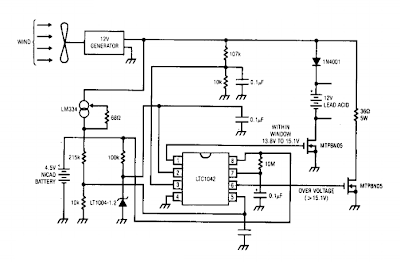
This is a Simple Wind battery Charger Circuit Diagram. The dc motor is used as a generator with the voltage output being proportional to its rpm. The LTC1042 monitors the voltage output and provides the following control functions. If generator voltage output is below 13.8 V, the control circuit is active and the Ni-Cad battery is charging through the LM334 current source. The lead acid battery is not being charged. 

If the generator voltage output is between 13.8 V and 15.1 V, the 12 V lead acid battery is being charged at about 1 amp/hour rate (limited by the power FET). If generator voltage exceeds 15.1 V (a condition caused by excessive wind speed or 12 V battery being fully charged) then a fixed load is connected limiting the generator rpm to prevent damage. This charger can be used as a remote source of power where wind energy is plentiful such as on sailboats or remote radio repeater sites. Unlike solar powered panels, this system will function in bad weather and at night.

Simple Wind battery Charger Circuit Diagram

Simple Wind battery Charger Circuit Diagram

[Continue reading...]

Sunday, December 22, 2013

9V Automatic Battery NiCd Charger

- 0 comments
This automatic NiCd charger for 9V NiCd batteries is using 555 timer properties and is very easy to build. Why is an automatic 9 volts NiCd battery charger? Because you can leave the battery for charging as much as you like: it will be always completely charged and ready for use when is needed. It wont be overcharged and it will not discharge.

9V Automatic Battery NiCd Charger Circuit Diagram :

nicd-charger-circuit-diagram

With the values presented in the circuit diagram, the battery charger NiCd circuit is suitable for 6V and 9V batteries. 9 volt types with 6 and 7 cells are charging with 20mA; P1 must be adjusted so that the NiCd charger disconnects after 14 hours. Window inferior level is set at 1V below this value with P2. 5V battery type with 4 or 5 cells are charged at 55mA. Again, with P1 adjust the NiCd charger circuit so it disconnects after 14 hours. Window inferior level must be set at 0.8V below this value.

Source: http://www.ecircuitslab.com/2012/08/9v-automatic-battery-nicd-charger.html

[Continue reading...]

Thursday, April 11, 2013

Making a Solar Energy Powered an iPhone Battery Charger

- 0 comments
The project was termed as Mighty Minty Boost as it was developed to function as iPod/iPhone charger with solar power. Aside from being small, it has a large battery capacity of 3.7V at 2000mAh and it accepts input power from 3.7V to 7V. As shown in the images below, it can become a compact USB power supply when the solar cell is removed after charging. The Velcro is used to secure the Mighty Minty Boost inside a backpack or messenger bag after unplugging the solar cell.

For faster charging, a larger solar cell can be attached to the bag. Enough power can be generated to fully charge an iPhone in about 5.5 hours and an iPod Touch in 4 hours using a slightly larger solar cell with 6V at 250mAh. The charger will automatically switch to trickle charging when the cell reaches full charge. The charging current is limited to 100mA when charging using the mini USB port and the charging is limited to 280mA when charging using the barrel plug jack

Hacks and Mods: iPhone Charger Powered Thru Solar Energy
.
The materials needed to build the charger include a small solar cell, Lithium Polymer battery charger, minty boost kit, adhesive backed Velcro, Altoids tin, connector/wire, and small double adhesive squares as shown in the images below. An input power that ranges from 3.7V to 7V maximum can be accepted by the single cell Lithium Polymer. In bright sunlight, the solar cell maxes out at approximately 5V at 100mA. A larger solar cell with 6V at 250mA can be used for faster charging.

Hacks and Mods: iPhone Charger Powered Thru Solar Energy

The images below show the assembly of minty boost kit where a JST connector is soldered to the minty boost PCB instead of connecting the battery holder in the kit. The minty boost circuit is allowed to connect to the Lithium Polymer battery charger circuit with this tiny connector. The minty boost is tested by connecting the battery pack and the charger circuit, the Lithium Polymer battery connects to the connector marked GND on the charger board and the minty boost connects to the connector marked SYS.

Hacks and Mods: iPhone Charger Powered Thru Solar Energy

To fit the charger, a notch is cut out of the other side of the Altoids tin and used double sided adhesive to secure the charging circuit to the bottom of the Altoids as shown below. The bottom of either one of the circuit boards should not touch the bottom of the Altoids tin while reconnecting the minty boost PCB and the battery to the charging circuit.

Hacks and Mods: iPhone Charger Powered Thru Solar Energy

Connecting or adding the solar cell can be done in different ways. Shortening the connector leads and plugging the barrel plug into the barrel jack on the charging circuit is one way. The other method is using another JST connector to replace the connector and plugging it into the third connector marked 5V on the charging circuit. Since there is no bog barrel plug sticking out of the side of the tin, using the second method is cleaner.

As shown in the photos below, some 2” Velcro was used to attach the solar cell to the top of the Altoids. To help protect the battery, a layer of clear packing tape was used for wrapping. N top of the two circuit boards, the battery pack is then set down. A red LED on the charger board will light up when the Mighty Minty Boost is set out in the bright sun. The iPod/iPhone/USB powered device can be connected once it is fully charged.

Hacks and Mods: iPhone Charger Powered Thru Solar Energy
[Continue reading...]

Wednesday, April 10, 2013

LM3914 battery level indicator

- 0 comments
LM3914 battery level indicator
Battery level indicator circuit is a circuit that is used to measure the battery voltage / battery. The main components of the battery level indicator circuit is an LM3914 IC. LM 3914 on Circuit battery level indicator is a monolithic IC that detects an analog voltage. And drive the 10 LEDs that produce a linear analog display on a given input voltage.

IC LM3914 is easy to get in the market and not expensive. IC LM3914 battery level indicator on the circuit is often encountered in a series of peak indicator audio signals in analog audio equipment. Battery level indicator circuit consists of IC LM3914, 10 pieces of LED, and a few resistors. The scheme of  battery level indicator can be seen below.

LM3914 battery level indicator

In the circuit of the battery level indicator on the supply circuit voltage taken from the battery / batteries through a switch. Didesaimn this circuit will only display the battery level when the switch is pressed. This is intended to save the battery voltage itself.
[Continue reading...]

Monday, April 8, 2013

12v Battery Charger Circuit

- 0 comments
The circuit may be accustomed charge 12V lead acid batteries.

Overview

Pin one of the LM317 IC is that the management pin that is employed to manage the charging voltage, Pin a pair of is that the output at that the charging voltage seems, Pin three is that the input to that the regulated DC offer is given.

The charging voltage and current is controlled by the electronic transistor (Q1), electrical device (R1) and POT (VR1). once the battery is 1st connected to the charging terminals, the present through R1 will increase. This successively will increase the present and voltage from LM317. once the battery is totally charged the charger reduces the charging current and also the battery are charged within the trickle charging mode.

Circuit


Notes
  • The input voltage to the circuit should be a minimum of 3V more than the expected output voltage. luminous flux unit 317 dissipates around 3V throughout its operation. Here I used 18V DC because the input.
  • The charging voltage may be set by victimization the POT (VR1).
  • The luminous flux unit 317 should be mounted on a sink.
  • All capacitors should be rated a minimum of 25V.
  • Youll be able to use crocodilian clips for connecting the battery to the charger.
[Continue reading...]
 
Copyright © 2012. Fast Diagrams - Posts · Comments
Powered by Blogger