Showing posts with label output. Show all posts

Monday, October 13, 2014

Muscular Bio Stimulator Circuit Diagram

- 0 comments

Parts:

R1______________10M 1/4W Resistor
R2,R3,R4_______100K 1/4W Resistors
R5,R7___________10K 1/4W Resistors
R6_______________1K 1/4W Resistor

C1,C2___________22pF 63V Ceramic Capacitors (See Notes)
C3______________22µF 25V Electrolytic Capacitor
C4,C5__________100nF 63V Polyester Capacitors
C6_______________1µF 63V Polyester, Multilayer Ceramic or Electrolytic Capacitor

IC1____________4060 14 stage ripple counter and oscillator CMos IC
IC2____________4040 12 stage ripple counter CMos IC
IC3____________4082 Dual 4 input AND gate CMos IC
IC4____________4075 Triple 3 input OR gate CMos IC
IC5____________4520 Dual binary up-counter CMos IC
IC6____________4001 Quad 2 input NOR Gate CMos IC

D1_____________5 or 10mm red LED

XTAL_________32.768 kHz Sub-miniature Watch crystal

P1_____________SPST Pushbutton
SW1____________2 poles 6 ways Rotary Switch
SW2____________SPST Toggle or Slide Switch

B1_______________9V PP3 Battery

Clip for PP3 Battery

Alternative Clock Parts:

R8_______________1K 1/4W Resistor
R9_____________330K 1/4W Resistor
R10_____________20K 1/2W Cermet or Carbon Trimmer
R11______________1K 1/2W Cermet or Carbon Trimmer

C7_______________1µF 63V Polyester Capacitor

IC7____________7555 or TS555CN CMos Timer IC

Circuit purpose:

A Pills Reminder is a device that operates a flashing LED (and/or a beeper) at a fixed hour interval. A choice of time-intervals as wide as possible is available with this circuit, namely 4, 6, 8, 12, 24 and 48 hours.

Operation Mode:

At first you must choose the hour interval by switching SW1 to the desired value, then apply power by means of SW2.
After the hour delay chosen has elapsed the LED will start flashing at 2Hz, i.e. two times per second. This status will last until pushbutton P1 is pressed: then the LED will turn off, but the circuit will continue its counting and the LED will flash again when the same hour interval as before is reached.
A noteworthy feature of this circuit, usually not found in similar devices, is that the internal counter is not reset when P1 is pressed: this allows a better time-interval precision.
Let us explain this feature with an example: suppose you have set the time interval to 24 hours and started the Pills Reminder at 8 oclock. Next day, at 8 oclock the LED will start flashing, but you, for some reason, notice the flashes at 8:10 and press P1 to stop the LED. With most devices of this kind, the counter will be reset, causing the LED to start flashing next day at 8:10 oclock.
This will not happen with this circuit and the LED will start flashing next day always precisely at 8 oclock even if you pressed P1 at 9 or 10 oclock.

Circuit Operation:

The clock of the circuit is made of a stable oscillator built around two inverters embedded into IC1 and a Watch crystal oscillating at 32.768kHz. This frequency is divided by 16384 by the internal flip-flop chain of IC1 and a 2Hz very stable clock frequency is available at pin #3 of this IC.
IC2 counter and IC3A 4 input AND gate are wired in order to divide by 3600 the 2Hz clock, therefore, a pulse every 30 minutes is available at the clock input of IC5.
The division factor of this IC is controlled by IC3B and the position of SW1A and B, selecting from six time-intervals fixed to 4, 6, 8, 12, 24 and 48 hours.
The set-reset flip-flop formed by IC6B and IC6C is set through IC4C each time a low to high transition is present at the pin of IC5 selected by SW1B cursor. IC6A and C4 provide to set the flip-flop also when a high to low transition is present at SW1B cursor.
When the flip-flop is set, IC6D is enabled and the 2Hz frequency available at pin #3 of IC1 is applied to pin #13 of IC6D causing the flashing LED operation. The flip-flop can then be reset by means of P1.
A master reset is automatically done at switch on by means of C6 and R7.

Alternative Clock:

Sometimes, the Watch crystal can be difficult to locate, or could be considered too expensive. For those willing to avoid the use of a Watch crystal and to accept less time accuracy, an alternative clock generator circuit is provided, directly oscillating at 2Hz, thus avoiding the use of divider ICs.
A CMos 7555 Timer IC generates a stable 2Hz square wave, whose frequency must be accurately set by means of two trimmers. R10 must be adjusted first for coarse tuning, then R11 for fine tuning.
Setting precisely the 2Hz frequency of this oscillator is a rather difficult task, and can be done with great patience and the aid of a clock, a chronometer or, best, a digital frequency meter capable of measuring very low frequencies.
In any case, after an accurate setup, this oscillator showed a very stable performance, not affected by battery voltage variations and an accuracy of about ±30 seconds per 24 hours interval.

Notes:

  • Wanting the utmost time precision and if a digital frequency meter is available, a 5-50pF 50V Ceramic Trimmer Capacitor can be used in place of C2. It must be adjusted in order to read exactly 32.768kHz on the meter display with the input probe connected to pin #9 of IC1.
  • A Piezo sounder (incorporating a 3KHz oscillator) can be added to provide a visual plus audible alert. It must be wired across pin #11 of IC6D and negative ground, respecting polarities. Remove D1 and R6 if the visual alert is not needed.
[Continue reading...]

Tuesday, December 24, 2013

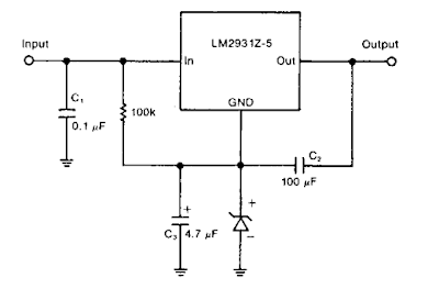
Zener Diode Increase Regulator Output Circuit Diagram

- 0 comments
A zener diode in the ground lead of a fixed pnp regulator varies the voltage output of that device without a significant sacrifice in regulation. The technique also allows the regulator to operate with output voltages beyond its rated limit.

Zener Diode Increase Regulator Output Circuit Diagram

Zener Diode Increase Regulator Output Circuit Diagram

[Continue reading...]

Sunday, April 7, 2013

Maximizing Solar Panel Efficiency and Output Power

- 0 comments
Improve Solar PV Panel Efficiency and Output Power
There are a number of means available to increase solar panel output and efficiency — some of which may be utilized by the serious experimenter. These are listed as follows:
Solar Cell Technology
There are a number of technologies being researched and there are continual advancements. Experimental technologies and highest efficiencies include:

  • Multi-cell gallium arsenide – 44%
  • Single cell gallium arsenide – 29%
  • Crystalline silicon - 25%
  • Thin film copper-indium-gallium-selenide – 20%
  • Emerging PV technologies (dye-sensitive cells etc.) – 11% (low efficiency, but very inexpensive)
Check out this link for an informative solar cell research chart:
http://upload.wikimedia.org/wikipedia/commons/7/71/PVeff%28rev121211%29.jpg
informative solar cell research chart
Unfortunately, we live in the real world and the highest efficiency technologies are either unaffordable or have not been put into production. As a result, the experimenter is generally stuck with crystalline silicon technology with efficiencies ranging from 15 to 21.5% — this is what I refer to as “practical efficiency.”
Fill factor
Fill factor is simply a fancy term for utilization of available surface area. Full utilization of fill area is required to obtain highest output for a given surface area. The fill factor ranges from about 70 to 90%. You have seen solar panels that utilize round or moon shaped PV cells — well, these have a lower fill factor than square cells. This is not really that important — all it means is that panels delivering a specific power may vary in dimensions somewhat. On the other hand, if attempting to maximize the amount of solar power out of a specific area, then fill factor is an issue.
Grade A, B, C, D
When purchasing name brand solar panels, you will be getting perfect grade A cells. If purchasing garage shop solar panels, the quality of its cells is unknown. If purchasing DIY solar cells, all grades are available, but beware — it is easy to get cheated on quality. If purchasing on eBay, check feedback ratings.
  • Grade A: No imperfections – output = 100% – (name brand panels)
  • Grade B: Cosmetic imperfections – output > 90% – (good for DIY panels)
  • Grade C: Contains chips and/or micro-cracks – output = 75 to 90% – (serious experimentation)
  • Grade D: Fallout – output = 25% to 75% – (just for messing around)
Check out this link just for messing around—note extremely low fill factor:
http://www.instructables.com/id/Make-a-high-powered-solar-panel-from-broken-solar
Note that micro-cracks effectively reduce the fill factor so that it takes a larger surface area (more cracked cells) to obtain the same power output. Micro-cracks can also cause localized heating and roof fires — beware!
For more info, check out http://reviews.ebay.com/Solar-Cell-Grading-A-B-C-D?ugid=10000000017991249
glazed solar panel
Solar Cells Glazing
For long life, solar cells must be protected from the elements (rain, snow, hail, bird dropping etc). Polycarbonate or low-iron glass is generally recommended due to high optical transmissivity — perhaps 90%. Surface coating treatments reduce reflections for even higher transmissivity. Ordinary window glass reduces the output by about 40% — not recommended. Note that my knowledge is weak in this area.
Solar Panel Orientation
For highest output, solar panels must be perpendicular to the sun’s rays. However, it is generally practical and common for roof-top installations to follow the roof pitch and orientation. For other types of fixed installations, the azimuth is oriented to the south and tilt adjusted for the winter sun. Note that solar power is minimized in the winter mostly due to the reduced daylight period; therefore that is the default for fixed orientation. While this is clearly not optimum in the summer, the longer daytime period more than compensates for the compromised tilt angle.
Check out this solar calculator http://energyworksus.com/solar_installation_position.html
Solar tracker
solar trackerSolar tracking is a great way of increasing the output power. It rotates the panel or array of panels so that they always directly face the sun. However, the larger the array, the more difficult will be the mechanics of this task. Some trackers are simply driven by a “clock” motor like a telescope so that it follows the sun (or wherever it is supposed to be in the cloudy sky). Others have active circuitry that adjusts the orientation for maximum power output. Others may be controlled by a shadow feedback signal technique.
Check out this DIY Solar Tracker
The optimum tilt angle changes slowly as the earth rotates on its axis, therefore it is not generally required to track this change automatically. The easiest way to handle this seasonable variable, is to go out and manually adjust the angle every month or so — not a difficult task.
Concentrators
Solar panel output power may be increased via a light concentrator such as a Fresnel lens or mirror. Note that such a lens must be substantially larger than the panel. Also, concentrators may not be practical for a large array, and orientation of the mirror creates an additional tracking problem. Output may be increased by perhaps 50%. Care must be taken to prevent overheating the panel.
Check out this brief video
Solar Charge Controls
Since the solar panel does not put out the correct voltage to charge a battery, it must be controlled via a solar charge controller to prevent battery overcharge. The series voltage regulator control wastes the excess power either by turning off the solar panel current or by dissipating the excess power in heat — that is the function of the heatsink in such controls. electroschematics.com has a number of these controls.

MPPT Controller
MPPT stands for Maximum Power Point Tracking. The MPPT control is different in that it does not turn the excess power into heat — it turns it into additional charge current so that if the solar panel is putting out 10A, the battery may actually be charging at a higher current (perhaps 12A). The control senses both input voltage and current, and then does some math with its microcontroller and makes adjustments accordingly in order to maximize power transfer. It uses switch mode technology.
On the other hand, when the battery is fully charged, it still turns off the solar panel. I was toying with the idea of what to do with this unused power, but have not come up with a really practical use other than perhaps to heat water in a hot water tank.
Here is a popular commercial MPPT control with a great description http://www.windsun.com/ChargeControls/MPPT.htm
Glossary of undocumented words and idioms (for our ESL friends)
transmissivity – noun – ability of a medium to transmit or pass electromagnetic energy — light in this case
garage shop – noun – small scale “bare bones” manufacturing operation (literally in a garage)
bare bones – adjective – simple, limited — literally all that is left after an animal carcass decays…
[Continue reading...]
 
Copyright © 2012. Fast Diagrams - Posts · Comments
Powered by Blogger