Showing posts with label simple. Show all posts

Saturday, November 8, 2014

Simple Cheap LED flasher

- 0 comments

This two LED flasher circuit uses any DC supply from 3V to 12V. Flash rate is controlled by R1,C1 and R2,C2. Larger values create slower fash rates, smaller values higher flash rates.
[Continue reading...]

Wednesday, November 5, 2014

Simple and Mini FM Receiver

- 0 comments
This is a very simple and mini fm radio receiver with good performances that works great even if the sensitivity is not too high. The working principle of this fm receiver may seem a little unusual. It is made of an oscillator (T2 and T3) that is synchronized with the received frequency of T1. This transistor works as a broadband preamplifier in VHF range.

Mini FM Receiver Circuit Diagram :

FM

The oscillator is adjusted between 87 … 108 MHz with C5. Because of the synchronization, the oscillator output will have the same frequency deviation as the received signal from the fm antenna. This deviations are caused by the broadcasted audio informations. The frequency modulated signal show up on P1 + R5. Low pass filter R6/C6 extracts the audio signal and then is amplifier by T4 … T6 and transmitted at the output through C9 capacitor.

The coil details are presented in the fm receiver circuit diagram. The radio receiver is adjusted on different stations with the help of C5. P1 potentiometer is adjusted untill the best reception is obtained. If we attach an audio amplifier and a speaker then this fm receiver can be made very compact as a pocket radio.


[Continue reading...]

Thursday, October 23, 2014

Simple Inverter with Two Transistors

- 0 comments
The series below is a simple inverter circuit that will change the voltage of 12v dc to 220v ac, with use drive transistor 32 as its tip.  Inverter circuit is very simple and easy to assemble and is perfect for just starting to learn to assemble electronic circuits, you can use the transformer 2A to produce about 20 watts output. Do not forget to install coolers in its transistors. good luck.
Simple
[Continue reading...]

Thursday, October 16, 2014

Simple Power Pulse Using by LM350 and NE555 Circuit Diagram

- 0 comments
This is a Simple Power Pulse Using by LM350 and NE555 Circuit Diagram. This circuit can use to drive lamp,power LED,DC motor etc. Adjust R5 for output amplitude.Adjust R1 for output power .

Power Pulse Circuit Diagram


The LM350 is adjustable 3-terminal positive voltage regulators is capable of supplying in excess of 3A over a 1.2V to 33V output range.This circuit requires 5-15V power supply.
[Continue reading...]

12V to 120V DC DC Converter Circuit

- 0 comments

12V to 120V DC DC Converter Circuit

Here is a simple DC DC converter schematic using a saturation-limited to push-pull converter. DC converter can be used to power the VCR from a car battery and glow plug light aircraft models from a 12V battery starter.

As a final amplifier of the DC DC converter is a pair of transistor MJE2955 and 2SC945 as oscillator to apply sufficient bias to the final amplifier transistors.

The 2SC945 is a bias switch for startup. When applying 12V power, this transistor applies enough bias to the power transistors to get the oscillation started. Soon later, the 100uF capacitor charges up, the transistor goes off, and the power transistors self-bias into cut-off, such that cross-conduction is eliminated. After removing power, the 6k8 resistor discharges the bias timing capacitor, as otherwise the circuit would be unable to restart!

The secondary rectifiers are ultrafast diodes. These are NOT 1N4007! And the 220nF capacitors for the secondary filter are no typos; the diodes deliver almost pure DC, since the oscillation waveform is square, so only some noise filtering is needed. No electrolytics are necessary here.

12V

DC DC Converter

Note the filters at both input and output, using ferrite cores. These are necessary to avoid polluting your environment with RF noise! Using these filters, and joining the input and output negative leads, this converter is very quiet and does not cause any problem in my combined HF, VHF and UHF station.

All ferrite cores (for the transformer and for the noise filters) are manufactured by Amidon Associates, and can be ordered directly from them in small quantities. Look for Amidon on the web. The 77-material core used for the transformer is less than ideal. A square-loop ferrite would work more efficiently! This one gets really warm, operating in saturation mode at 25 kHz. But it has worked well enough for two years now. The filter cores, on the other hand, are well chosen, so try to use the exact ones.

For all windings, the schematic states the number of turns. “7t” means 7 turns. As the transformer is quite small for the involved power, use as thick a wire as you can fit, leaving about half of the space for the 2×7 turns primary winding, and the other half for the secondary, while the feedback winding can be made from very thin wire.

The transistors do not need any heat sinks. They are large enough without, and they need to dissipate little heat!

[Continue reading...]

Thursday, October 9, 2014

Dome Lamp Dimmer circuit and explanation simple

- 0 comments

Many autos run power to lamps with only one wire using the car body for the return current path so the dimmer must interrupt the positive lead as shown. Simply cut the wire leading to the lamp and connect the lamp end to the collector of the TIP32 and connect the battery end to the circuit power input. Run an additional ground wire to the auto chassis from the circuit. This ground wire will not carry much current and may be a smaller gauge. There are times when a little light inside the car would greatly assist one of the passengers but the dome light is too bright for safe driving.

The dimmer circuit in fig. 1 may be added to an existing dome light or included with a new passenger spot lamp. The upper op-amp generates a 700 Hz sawtooth waveform which is compared to a setpoint voltage by the lower op-amp. When the sawtooth voltage is above the setpoint, the transistors turn on supplying current to the bulb. The setting of the potentiometer determines the width of the pulses sent to the lamp and therefore the average voltage. The lamp is dim when the potentiometer is set near the higher voltage. Since the TIP32 switches on and off instead of simply dropping the voltage like a power rheostat, the power it dissipates remains low and a heat sink is not necessary.
[Continue reading...]

Thursday, September 25, 2014

Simple Time Delay Circuit Using Op Amp

- 0 comments
lC1a is provided with re- sistive and capacitive feedback to form an integrator with initial conditions. lC1b is in an "open loop" mode so that its output is either high or low depending on its inputs, and changes state when the output of lC1a goes more negative than the voltage set at ZD2.
When . the output of IC1 b goes positive the transistor Q1 biases hard on switching the SCR on. Diodes D1 -D4 are to make the SCR conduct on both halves of the mains wave form. The delay period is set by the components ZD1, ZD2;·C, RVl, and  R. lf ZD1 is chosen to be OV5 and ZD2 at 5V, then the maximum delay period is given by T= 10CR
RV1 = ZD2/ZD1 * R<10.r

 The meter is a voltrneter with as fsd equal to the value of ZD2. The switch then operates when the meter reaches fsd. The meter can therefore be calibrated to show remaining delay with OV equal to T and fsd equal to zero. SW2 changes round the inputs of the op—amp so that the output either swings from high to low, or, low to high. SW3 is to reset the time delay which it does by discharging the capacitor. ZD3 should be chosen  to be a value slightly higher than ZD2, this is to stop the capacitor charging beyond a set limit and therefore overloading the meter. SW1 is the run—hold switch. When the switch is at +12 volts the integrator charges the capacitor. When the switch is set to OV the charging of the capacitor is stopped until the switch is set back to 12 volts. . Q1 is a buffer to avoid loading on the IC and to trigger the SCR. The supply voltage should be 12-0-12 and does not need to be well smoothed as the zener diodes set the timing function,


Simple Time Delay Circuit Using Op Amp


[Continue reading...]

Wednesday, September 24, 2014

Simple Tachometer Circuit or Revolution Counter Circuit

- 0 comments
The explained idea of a simple tachometer circuit can be used as a revolution counter tester for determining or setting the correct optimal engine speed which may ensure maximum engine efficiency from the vehicle. The pulses emanating from the contact breaker are shaped and limited by Fl2/R5/ D2. Transistor T2 conducts only when the contact breaker is open, because the full battery voltage is then present at the input (PL2) of the rev counter (see figure 48). Capacitor C2 is then discharged rapidly through R6 and T2. When T2 is cut off when the contact breaker closes, C2 charges only slowly via R4.

This ensures that the trailing edge caused by the closing of the contact breaker is applied to the next stage as a steep pulse, while the noise spikes are suppressed by the slow charging of C2. It follows that C2 must be carefully matched to the particular car engine. Diodes D4 and D5 protect the trigger input of IC1 against too high positive and negative voltages. The real heart of the circuit is C1: this versatile counter is connected as a monostable multivibrator (MMV). After every trigger pulse at pin 2 (negative voltage jump applied via C4) it generates an output pulse of constant period which may be preset with P1. Unfortunately, the counter auto-triggers if pin 2 is still logic low after the output pulse period has lapsed, and because of that R8 ensures that C4 can only pass very narrow trigger pulses.

The resistor and capacitor form a so called differentiating network (see figure 49).  It would now be possible to connect a suitable moving-coil meter to the output (pin 3) of IC1. Because of the inertia of this instrument, the individual output pulses (pulse width = O.7C7 (P1+R11) sec) are averaged (integrated). The meter reading corresponds exactly to the average value of the pulse height (see figure 50) and is therefore  provided Pl has been adjusted correctly proportional to the instantaneous engine speed.

The comparator, A3, following IC1 has no inertia and the output pulses from IC1 must therefore be smoothed’: this is effected by two integrating networks, R7/C5 and R9/C8 (see figure 51). Across C8 there exists therefore a reasonably constant direct voltage (the remaining ripple caused by the original pulses may be ignored) which is directly proportional to the engine speed (see figure 52). This direct voltage is set to 5 V at maximum engine speed during the calibration which follows later.

The following image shows the simple tachometer circuit design


The waveform images can be verified from the folowing images.


[Continue reading...]

Tuesday, September 9, 2014

Simple 5 Band Equalizer

- 0 comments
This circuit uses a single chip, IC BA3812L to make 5 band graphic equalizer in audio hi-fi system. BA3812L IC is a 5-point graphic equalizer that has all functions integrated on a single IC. This IC is composed of five tone control circuit and input and output buffer amplifier. BA3812L have low distortion, low noise, and wide dynamic range, and is ideal for a variety aperanti Hi-Fi stereo. He also has a wide operating voltage range (3.5V to 16V), meaning he could be adapted for use on most stereo equipment.
5

The five center frequencies are independently set using external capacitors, and therefore act as an output stage buffer amplifier and tone control section is a series of its own, it is possible to do fine control over the frequency bandwidth. By using two BA3812Ls, you can create a 10-point graphic equalizer. Great header and pieces can be set by external components.

The recommended power supply of 8V, but this circuit can work well for supply voltage 9V. Limit the maximum voltage is 16V.

The circuit is given in the diagram operates in around 5 frequency bands:
100Hz , 300Hz , 1kHz , 3kHz , 10kHz
[Continue reading...]

Tuesday, September 2, 2014

Simple 12 Volt Charger Wiring diagram Schematic with LM350

- 0 comments
Simple 12 Volt Charger Circuit Diagram with LM350.The strength supply routine structure is developed as a resource of continuous present with adverse heat range coefficient. Transistor Q1 (BD 140) is used as a heat range indicator. transistor Q2 is used to avoid the strength supply from discharging through R1 when strength is out of stock. Getting routine is developed depending on the LM350 present regulator IC. The result present of the battery charger can be altered between 13-15 V by various the POT R6.

 Simple 12 Volt Charger Circuit Diagram with LM350


LM350 will try to keep the present decrease between the feedback pin and result pin at a continuous value of 1.25V. So there will be a continuous present circulation through resistor R1. Q1 act here as a heat range indicator with the help of R6/R3/R4 elements that are more or less manages the platform present of Q1. As relationship emitter / platform of transistor Q1, the same as other semiconductors, containing the heat range coefficient of-2mV / ° C, the present result will also display a bad heat range coefficient. This one is just a aspect of 4 huge, because the difference of the emitter / platform of Q1 is increased by a aspect of category P1/R3/R4. This causes some-8mV / ° C. LED will lighting whenever strength is available.
[Continue reading...]

Friday, January 10, 2014

Simple Universal Laboratory Power Supply Circuit Diagram

- 0 comments
This is the Simple Universal Laboratory Power Supply Circuit Diagram. The value of the design lies in the use of IC1, an LM317HVK adjustable s.eries-pass voltage regulator, for broad-range performance remainder supplies voltage-setting and current-limiting functions. 

The input to ICI-comes from the output of BR1, which is filtered by CI and C2 to about +60 Vdc, and the input for current-sense comparator IC2 comes from BR2, which also acts as a negative bias supply for regulation down to ground.

Universal Laboratory Power Supply Circuit Diagram

Universal Laboratory Power Supply Circuit Diagram


Simple Universal Laboratory Power Supply Circuit Diagram
[Continue reading...]

Thursday, December 26, 2013

Simple Active ir Motion Detector Circuit Diagram

- 0 comments
To explore how different motion detectors operate.To successfully build and test an ambient-light-ignoring active IR motion detector.

Background
 There are a wide variety of motion detectors available currently. To allow a better understanding of motion detectors,the following section provides a detailed description of a few different types.

Ultrasonic Motion Detectors
Ultrasonic transducers can be used to detect motion in an area where there are not supposed to be any moving objects.This type of motion detector is most commonly used in burglar alarm systems since they are very effective in this application.


 Figure 1 shows the operation of an ultrasonic motiondetector. There are tw1o transducers: one emits an ultrasonicwave and the other picks up reflections from the differentobjects in the area. The reflected waves arrive at the receiverin constant phase if none of the objects in the area are moving.If something moves, the received signal is shifted in phase. 

A phase comparator detects the shifted phase and sends a triggering pulse to the alarm.Ultrasonic motion detectors have certain advantages and disadvantages when compared with other types of motion detectors. The main advantages is that they are very sensitive and extremely fast acting. However, the largest problem with this type of motion detector is that it sometimes responds to normal environmental vibration that can be caused by a passing car or a plane overhead. Some types of motion detectors use infrared sensors to avoid this problem, but even these detectors have some problems.

 Passive Infrared Motion DetectorIn passive infrared motion detectors, a sensorcontaining an infrared-sensitive phototransistor is placed in thearea to be protected. Circuitry within the sensor detects theinfrared radiation emitted by the intruder`s body and triggersthe alarm. 

The problem with using this type of detector is that it can be falsely triggered by warm air movement or other disturbances that can alter the infrared radiation levels in an area. In order to prevent this problem, newer systems use tw1oinfrared sensors which monitor different zones within a protected area. Logic within system triggers the alarm only when the tw1o zones are activated in sequence, as would occur if a person walked through the protected area.

Active Infrared Motion Detector


Figure 2 shows the operation of an active infrared motion detector. In the active system each sensor consists oftw1o housings. One housing contains an infrared-emitting diode and an infrared-sensitive photo transistor. The other housing contains an infrared reflector.When positioned in front of an entrance to a protected area, the tw1o housings establish an invisible beam. A person entering the area interrupts the beam causing an alarm to be triggered. An active motion detector is much more reliable than a passive one, but it requires careful alignment when it is installed. The detector can be falsely triggered if one of the housings moves slightly and causes a discontinuous beam.

Project
 For our project, we decided to construct an activeinfrared motion detector. Originally, we wanted to build both anIR and an ultrasonic detector, but we decided that an ultrasonicdetector would require too much time for a three week project.However, we also decided that just building an IR motiondetector would probably be a trivial exercise. 

So, we decided to expand on the concept by building an ambient light ignoring motion detector.This type of motion detector uses the same basic concept as the active infrared motion detector. An interruption in a 5kHz modulated pulsating beam that is transmitted by an infrared diode and received by an infrared transistor sets off the alarm. A schematic of this motion detector is given in Figure 3.

Simple Active ir Motion Detector  Circuit Diagram

 Figure 3. Ambient-Light-Ignoring Active Motion Detector

The circuit on the left is the transmitter circuit that establishes a 5 kHz modulated infrared beam. As you can see from the schematic of the receiver circuit, a resonance-handbarrow amplifier reduces the detector`s sensitivity to stray light. C1 and L1 in IC2A`s feedback loop cause the op amp to pass only those frequencies at or near the LED`s 5 kHz modulation rate. IC2B`s output increases when the received signal is sufficient to drop the negative voltage across C2 below the reference set by R2. The output of this circuit is then attached to some load resistance, which can be an alarm or, for demonstration purposes, an LED.
[Continue reading...]

Wednesday, December 25, 2013

Simple Wind battery Charger Circuit Diagram

- 0 comments
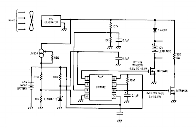
This is a Simple Wind battery Charger Circuit Diagram. The dc motor is used as a generator with the voltage output being proportional to its rpm. The LTC1042 monitors the voltage output and provides the following control functions. If generator voltage output is below 13.8 V, the control circuit is active and the Ni-Cad battery is charging through the LM334 current source. The lead acid battery is not being charged. 

If the generator voltage output is between 13.8 V and 15.1 V, the 12 V lead acid battery is being charged at about 1 amp/hour rate (limited by the power FET). If generator voltage exceeds 15.1 V (a condition caused by excessive wind speed or 12 V battery being fully charged) then a fixed load is connected limiting the generator rpm to prevent damage. This charger can be used as a remote source of power where wind energy is plentiful such as on sailboats or remote radio repeater sites. Unlike solar powered panels, this system will function in bad weather and at night.

Simple Wind battery Charger Circuit Diagram

Simple Wind battery Charger Circuit Diagram

[Continue reading...]

Monday, December 23, 2013

Simple Precision full wave Rectifier Circuit Diagram

- 0 comments
The circuit provides accurate full wave rectification. The output impedance is low for both input polarities, and the errors are small at all signal levels. Note that the output will not sink heavy current, except a small amount through the 10K resistors. Therefore, the load applied should be referenced to ground or a negative voltage. Reversal of all diode polarities will reverse the polarity of the output

Since the outputs of the amplifiers must slew through two diode drops when the input polarity changes, 741 type devices give 5% distortion at about 300 Hz.


Precision full wave Rectifier Circuit Diagram

 Sourced By: http://circuitsstream.blogspot.com/2013/07/precision-full-wave-rectifier-circuit.html
[Continue reading...]

Tuesday, May 28, 2013

How to make a simple motor

- 0 comments
This is a simple moter circuit.These pictures show how to make a simple motor.first of all you should take two plates that I have mentioned bellow.and set it up on a wooden plate as picture 3 has shown.Then after take coils and wrap it around the plastic stick. When the stick rotates the coil should have a contact with the current supplier so after wrapping place the coil as picture shows.place a magnet middle of the stick as picture shows.


[Continue reading...]

Sunday, May 26, 2013

Simple game for kids

- 0 comments
This is simple game for kids.You can propose your Friends to bring this ring one end to another end.while your friends are bringing this ring one end to another end if it touch the coil the bulb will light up.Then he loses the game.the chance goes to another.If one could take the ring to another side that one can win this game.this method is so impotent to check you nerves.if you can do this patiently you have good health condition
[Continue reading...]

Friday, April 12, 2013

Simple Rain Alarm

- 0 comments
GIVES BEEP WHEN WATER IS IN CONTACT WITH THE WIRE

Water is a conductor of electricity. When water is in contact with the probe then there is a flow of current which reaches to the base of Q1. Transistor Q1 is a NPN transistor which conducts. With the conduction of Q1 electron reaches to Q2 which is a PNP transistor .Q2 also conducts and current flows through the speaker. In a speaker there is inductive coil which causes motion in one direction and also produce induce current which is in opposite direction to the flow of current this induce current in the form of pulse flows through a capacitor, resistance and switches off Q1 and relax .this process repeats again and again till probe is in contact with water or we can say there is a oscillation in the circuit thus speaker diaphragm vibrates and gives a tone. Frequency of the circuit depends on the value of Speaker Coil impendence, Capacitor and Resistance Value.


[Continue reading...]

Simple Ignition Timer Schematic

- 0 comments
This circuit is a tester for flywheel based ignition systems in small aeroplane engines. Basically the same ignition coils are also seen in other small combustion engines used in/on mopeds and lawn mowers  in brief, engines without a battery. The part to be tested comprises a primary coil in parallel with the contact breaker. The timing of this contact breaker has to be adjusted correctly.
Since the coil’s primary has a very low resistance it is difficult to determine whether the contact breaker is open or closed.  However, you can determine that reliably with this circuit, using an LED and a beeper. The circuit is implemented twice because aviation engines (Cessna, Piper and similar) always have two ignitions in parallel to increase reliability. For two-cylinder engines, well the purpose is obvious.
Ignition Timer Circuit Diagram
The circuit consists of a 555 and a few transistors. The 555 supplies a square wave of about 3000 Hz. This signal goes to power transistors T1 and T2; these can supply quite a bit of power and are robust enough to withstand the voltage transients from the big coils. The test connection (K2 and K3 respectively) are connected in parallel with the contact breaker to be tested, which itself is in parallel with the ignition coil. The frequency of 3000 Hz is either short circuited by the contact breaker or if the points are open  is amplified somewhat by the resonance of the coil itself.

This allows you to reliably detect the difference bet ween a closed and open contact breaker, despite the low resistance of the coil, which is in parallel with it. When the contact breaker is open the amplified pulses will turn on T3 and T4 respectively, so that the relevant LEDs turn on and the buzzer will sound.

The components are not critical, but do use a sensitive type for the piezo buzzer. The power supply is 3 V (2 times AA or AAA batteries). Link
[Continue reading...]

Wednesday, April 10, 2013

Simple Pseudo Random Glitter

- 0 comments
A question recently asked on the Elektor website forum was how to make several white LEDs ‘sparkle’. The helpful author has not only provided a useful suggestion (use a random effect), but also devel-oped a suitable circuit and even designed a PCB layout. You can download the Eagle files for this from the Elektor website page for this article (www.elektor.com, archive # 080329-1.zip).

But first let ’s consider the basic question: artificial sparkling or glittering can best be simulated by having the different light sources switch on randomly at a par ticu-lar frequency. Surprisingly enough, it is not all that easy to generate truly random se quencesele ctronically. However, the electronic ran-domness does not necessarily have to be perfect for glitter applications. Patterns that appear to be random are suf-ficient for the desired visual impression.
LED Circuit Diagram

Based on this principle, the author uses two 556 timer ICs to generate signals whose frequencies (850 Hz for IC1a and 180 Hz for IC1b) can be divided by each other with-out yielding an integer divisor. A decimal counter oper-ated in an unconventional manner uses these two signals to produce a constantly pseudo-random pattern on its ten outputs, which repeats itself only very infrequently. This behaviour is obtained by applying the higher frequency signal to the CLK input of counter IC2, with the CLK Inhibit input on pin 13 being driven by the lower-frequency signal. The result is ‘genuine pseudo-random’ blinking.

LEDs can be connected directly to the ten outputs, since a CMOS output can anyhow only supply a few milli ampères. However, it is recommended to use series resistors (2.2 kΩ to 4.7 kΩ) to reduce the load on the IC out-puts if the supply voltage is higher than 10 V. If you want to have more than ten LEDs glitter, you can naturally build several copies of this circuit. Link
Author : Hans-Jürgen Zons - Copyright : Elektor
[Continue reading...]

Simple 12V to 220V 100W Transistor Inverter Diagram

- 0 comments
Simple 12V to 220V 100W Transistor Inverter  Diagram
Simple 12V to 220V 100W Transistor Inverter  Diagram
[Continue reading...]
 
Copyright © 2012. Fast Diagrams - Posts · Comments
Powered by Blogger