Showing posts with label build. Show all posts

Thursday, November 13, 2014

How to Build 12 Volt DC Fluorescent Lamp

- 0 comments
A number of people have been unable to find the transformer needed for the Black Light project, so I looked around to see if I could find a fluorescent lamp driver that does not require any special components. I finally found one in Electronics Now. Here it is. It uses a normal 120 to 6V stepdown transformer in reverse to step 12V to about 350V to drive a lamp without the need to warm the filaments.12 Parts:C1 100uf 25V Electrolytic Capacitor
C2,C3 0.01uf 25V Ceramic Disc Capacitor
C4 0.01uf 1KV Ceramic Disc Capacitor
R1 1K 1/4W Resistor
R2 2.7K 1/4W Resistor
Q1 IRF510 MOSFET
U1 TLC555 Timer IC
T1 6V 300mA Transformer
LAMP 4W Fluorescent Lamp
MISC Board, Wire, Heatsink For Q1Notes:
  1. Q1 must be installed on a heat sink.
  2. A 240V to 10V transformer will work better then the one in the parts list. The problem is that they are hard to find.
  3. This circuit can give a nasty (but not too dangerous) shock. Be careful around the output leads.
[Continue reading...]

Wednesday, October 15, 2014

Build a Fly back Transformer Driver Circuit Diagram

- 0 comments
This is an efficient flyback driver for modern cylindrical rectified television flybacks. Many sites doesnt provide circuits driving these transformers, they simply say that they are bad.

I dont agree. In fact I built this circuit. I spent a lot of time for finding resonant frequency (around 15Khz) and duty cycle. These transformers best work at around 90% duty cycle. You may notice corona breakdown at terminals and pfffff sound (as well as the ozone smell) when adjusting the off time trimmer to near 500-300 ohms. Of course it will work for other tipes of flyback as frequency and duty cycle have a large range.

 Flyback Transformer Driver Circuit Diagram


Flyback


Frequency range can be increased using multiposition switch for other values of C3 capacitor ,for example 2 nF for 80KHz-200000KHz, but didnt found flybacks with so high resonant frequencies, in addition with higher values of c3 , eg 200nF, 2uF the
frequency will drop making possible the use of ignition coils, and rectified power transformers @50Hz to charge high voltage electrolitic caps at 300-400V). Unfortunately my ignition coil died because insulation breakdown (too long drawn arcs)...
I was able to power a small (20cm) Spark Gap tesla coil Using these dc rectified flybacks to charge primary tank capacitor.
The operation is simple
The 555 is wired as an astable and the capacitor is charged only through the 4,7Kohm trimmer (notice the diode) and discharged only through the 2.2 Kohm trimmer, making the duty cycle full adjustable. The square wave is then feed in a totem pole made up of a 2N3904 and a 2N3906, which are cheap, and easy to find. The totem pole ensures the gate being charged and discharged very fast (approx 50nS i think). The IRF840 is a cheap (i found it for 4euros) reliable and powerful power mosfet, it has current capability of 8 A continuous and 32A pulse, 800V drain source voltage, protecting internal zener diode. There is a snubbing network to ensure that voltage spikes are kept low (unless the insulation of the transformer start to leak) protecting both transistors and 555 IC. 100 ohm is a compromise between decay time and voltage spike.
Comments and specifications:
The 100 ohm snubber must me a 5W resistor, or it will burn at long operations
The led is only for safety purposes
Use a dead man switch (pushbutton) for safety
The power supply must supply at least 2-3 A if you want decent arcs (20000 KV)
Dangers:
The flyback driven in this way can supply a significant current, aldough the heart fibrillation starts at 30mA
I recommend caution to avoid painful arc-burns.
The arc is a hot plasma, never operate the circuit in presence of flammable substances.
Charging high voltage capacitors is a serious life threat, so if you arent unexperienced just draw arcs and no more

This device when rectified generates static voltage that can be a little annoying.... (or fun, i sprayed with corona a plastic pen from positive terminal and then i was able to attract little pieces of paper)
Disclaimer:
I dont assume any responsibility of the damages or discruptions dove by this device, to persons or things. Any irresponsable action would be a serios danger. This is high voltage threat it with respect.

author: Jonathan Filippi
[Continue reading...]

Friday, December 27, 2013

Build a Thermo Fan To Keep Your Amp Cool Circuit Diagram

- 0 comments
How to Build a Thermo-Fan To Keep Your Amp Cool Circuit Diagram


 Thermo-Fan To Keep Your Amp Cool Circuit Diagram

Build a Thermo-Fan To Keep Your Amp Cool Circuit Diagram

[Continue reading...]

Build a 60Hz Power Inverter Circuit Diagram

- 0 comments
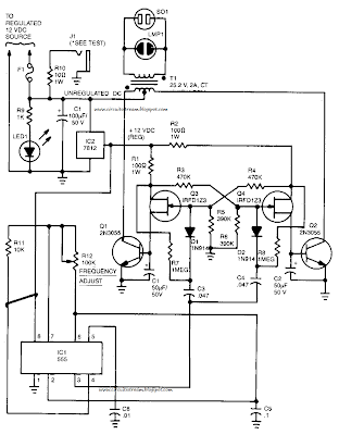
Hi Friends to we build a simple 60Hz Power Inverter Circuit Diagram.In the 60Hz Power Inverter Circuit Diagram Capacitor C5 and potentiometer R12 determine the frequency of the output signal at pin 3 of IC1, the 555 oscillator. The output signal is differentiated by C3 and C4 before it`s input to the base of power transistors Q1 and Q2 via diodes D1 and D2, respectively. 

The signal from !C1 is adjusted to 120Hz, because the flip-flop formed by transistors Q3 and Q4.divides the frequency by 2.When Q3 is on, the base of Q1 is connected via R1 to the regulated 12-V supply. Then, when the flipflop changes states, Q4 is turned on and the base of Q2 connected to the 12-V supply through R2. The 100 mA base current allowsQ1 and Q2 to alternately conduct through their respective halves to the transformer`s secondary winding. 

 60Hz Power Inverter Circuit Diagram

60Hz Power Inverter Circuit Diagram


To eliminate switching transients caused by the rapid switching of Q3 and Q4, capacitors C1 and C2 filter the inputs to the base of Q1 and Q2 respectively. Power for the unit comes from an automobile`s 12V system or from a storage battery. The power is regulated by IC2, a 7812 regulator. LED1, connected across the 12-V input, can be used to indicate whether power is being fed to the circuit. The neon pilot lamp, LMP1, shows a presence or absence of output power.


[Continue reading...]

Sunday, December 22, 2013

Build a Stand by Power Circuit Diagram for Non Volatile Cmos Rams

- 0 comments
This is  a simple Stand by Power Circuit diagram for Non Volatile Cmos Rams. To prevent loss of data when a CMOS RAM is switched from normal operation (Vcc = 5 volts) to stand-by mode (Vcc = VBAT) it must be ensured that the CS pin goes near the Vcc rail at all times. 

Ac coupling to the chip select is made through capacitor C, breaking the dc current path between Vqq (and hence VBAT) and the decoder output. So, whatever the impedance state of the decoder in power down, the battery will provide current only for the RAM, low enough to keep the voltage at CS near to V^.

Power Circuit Diagram

Build a Stand by Power Circuit Diagram for Non Volatile Cmos Rams Circuit diagram

[Continue reading...]
 
Copyright © 2012. Fast Diagrams - Posts · Comments
Powered by Blogger