Showing posts with label dc. Show all posts

Thursday, November 13, 2014

How to Build 12 Volt DC Fluorescent Lamp

- 0 comments
A number of people have been unable to find the transformer needed for the Black Light project, so I looked around to see if I could find a fluorescent lamp driver that does not require any special components. I finally found one in Electronics Now. Here it is. It uses a normal 120 to 6V stepdown transformer in reverse to step 12V to about 350V to drive a lamp without the need to warm the filaments.12 Parts:C1 100uf 25V Electrolytic Capacitor
C2,C3 0.01uf 25V Ceramic Disc Capacitor
C4 0.01uf 1KV Ceramic Disc Capacitor
R1 1K 1/4W Resistor
R2 2.7K 1/4W Resistor
Q1 IRF510 MOSFET
U1 TLC555 Timer IC
T1 6V 300mA Transformer
LAMP 4W Fluorescent Lamp
MISC Board, Wire, Heatsink For Q1Notes:
  1. Q1 must be installed on a heat sink.
  2. A 240V to 10V transformer will work better then the one in the parts list. The problem is that they are hard to find.
  3. This circuit can give a nasty (but not too dangerous) shock. Be careful around the output leads.
[Continue reading...]

Thursday, October 16, 2014

12V to 120V DC DC Converter Circuit

- 0 comments

12V to 120V DC DC Converter Circuit

Here is a simple DC DC converter schematic using a saturation-limited to push-pull converter. DC converter can be used to power the VCR from a car battery and glow plug light aircraft models from a 12V battery starter.

As a final amplifier of the DC DC converter is a pair of transistor MJE2955 and 2SC945 as oscillator to apply sufficient bias to the final amplifier transistors.

The 2SC945 is a bias switch for startup. When applying 12V power, this transistor applies enough bias to the power transistors to get the oscillation started. Soon later, the 100uF capacitor charges up, the transistor goes off, and the power transistors self-bias into cut-off, such that cross-conduction is eliminated. After removing power, the 6k8 resistor discharges the bias timing capacitor, as otherwise the circuit would be unable to restart!

The secondary rectifiers are ultrafast diodes. These are NOT 1N4007! And the 220nF capacitors for the secondary filter are no typos; the diodes deliver almost pure DC, since the oscillation waveform is square, so only some noise filtering is needed. No electrolytics are necessary here.

12V

DC DC Converter

Note the filters at both input and output, using ferrite cores. These are necessary to avoid polluting your environment with RF noise! Using these filters, and joining the input and output negative leads, this converter is very quiet and does not cause any problem in my combined HF, VHF and UHF station.

All ferrite cores (for the transformer and for the noise filters) are manufactured by Amidon Associates, and can be ordered directly from them in small quantities. Look for Amidon on the web. The 77-material core used for the transformer is less than ideal. A square-loop ferrite would work more efficiently! This one gets really warm, operating in saturation mode at 25 kHz. But it has worked well enough for two years now. The filter cores, on the other hand, are well chosen, so try to use the exact ones.

For all windings, the schematic states the number of turns. “7t” means 7 turns. As the transformer is quite small for the involved power, use as thick a wire as you can fit, leaving about half of the space for the 2×7 turns primary winding, and the other half for the secondary, while the feedback winding can be made from very thin wire.

The transistors do not need any heat sinks. They are large enough without, and they need to dissipate little heat!

[Continue reading...]

Tuesday, December 24, 2013

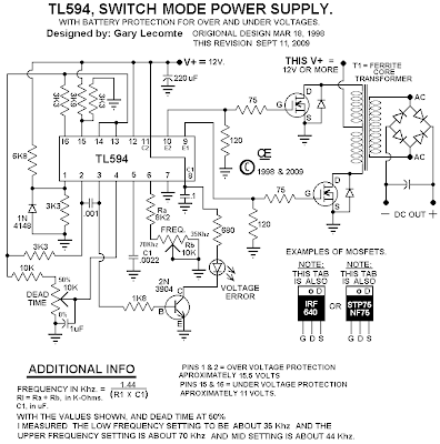
TL594 12V DC Switch Mode Power Supply Rise

- 0 comments
Basic Of Switch Mode Power Supply
In recent years, the use of switch mode power supply (SMPS) has become more comon as more applications demand for greater power eficiency. It makes use of semiconductor (mostly MOSFET) fast switches to switch DC input that has been rectified at high frequency. The advantages of high frequency switching are that it reduces the size of inductor, capacitors & transformer used. Other advantages of switching power supply over linear power supply are :

1) High Efficiency (up to 90% and above for nice design).
2) Output can be higher than input.
3) Able to operate over a variety of input power supply.
4) Able to have over output.

The setback of using SMPS compared to linear power supply is that it generates electrical noise which contributes to electromagnetic compatibility design issues & more part count.

Buck Converter SMPS
The SMPS circuit below from Power Integration makes use of LNK304 as its high frequency switch. Take note that this circuit is non isolated type which means that the output is not electrically isolated from the input & all testing ought to be completed using an isolation transformer to provide the AC line input to the board.

Make positive that you have electrical safety knowledge & experience before you embark on doing this project.

12V DC Switch Mode Power Supply Circuit Diagram


12V DC Switch Mode Power Supply Circuit Diagram


[Continue reading...]

Sunday, April 7, 2013

Transformer Voltage Booster Circuit DC DC Step Up Switching Regulator Using Transistors

- 0 comments
A DC-to-DC step-up converter is traditionally implemented using transformer, working by converting the DC voltage to AC Voltage, step-up it using transformer, then rectify and filter the transformer’s output to get a higher DC voltage. Using a switching method, we can step-up a voltage without a transformer. We just need an inductor which is driven by a switching transistor to boost the voltage. This is the figure of the circuit.


The most interesting this is that circuits use a discrete component: no integrated chip is required, only few transistors with few passive components. Because the switching topology is a boost converter, this circuit cannot be operated as step-down regulator, so the output will always be higher than the input. The voltage output is depend on the load because the feedback mechanism, through the zener diode, will maintain the output at about 14 volt, regardless the voltage input variation and load current variation. The current from the voltage divider will flow through the zener diode if the output goes higher than the nominal value, and this condition will stop the oscillator built around the 2N3904 transistors. Stopping the oscillator will drop the output voltage and thus maintain the required voltage level at the output. This transistor (Q1, Q2, and Q3) form a Schmidt trigger that drive the final transistor Q4 (the switching transistor 2N3053).

This circuit is suitable for battery booster, if you need to run your 12 volt equipments on your old car that is provide only a 6V supply from the battery. The output of this voltage double can be adjusted by changing the voltage divider, or for easier adjustment, you can replace the 4,7K resistor with a 5K potentiometer. Using a good inductor (low resistance), you can achieve up to 80% efficiency, and up to 2 Watt power can be delivered to the load. [Circuits schematic diagram source: Bill Bowdens circuit collection]

[Continue reading...]
 
Copyright © 2012. Fast Diagrams - Posts · Comments
Powered by Blogger