Showing posts with label explanation. Show all posts

Sunday, November 2, 2014

ic 555 Infra red Light Barrier Diagram Circuit

- 0 comments
This is a short-range light barrier for use as an intruder alarm in doorposts, etc. The 555 in the transmitter (Figure 1) oscillates at about 4.5 kHz, supplying pulses with a duty cycle of about 13% to keep power consumption within reason. Just about any infra-red LED (also called IRED) may be used. Suggested, commonly available types are the LD271 and SFH485. The exact pulse frequency is adjusted with preset P1. The LEDs are pulsed at a peak current of about 100 mA, determined by the 47 Ω series resistor. In the receiver (Figure 2), the maximum sensitivity of photo-diode D2 should occur at the wavelength of the IR LEDs used in the transmitter. You should be okay if you use an SFH205F, BPW34 or BP104. Note that the photo-diode is connected reverse-biased! So, if you measure about 0.45 V across this device, it is almost certainly fitted the wrong way around.

transmitterThe received pulses are first amplified by T1 and T2. Next comes a PLL (phase lock loop) built with the reverenced NE567 (or LM567). The PLL chip pulls its output, pin 8, Low when it is locked onto the 4.5 kHz ‘tone’ received from the transmitter. When the (normally invisible) light beam is interrupted (for example, by someone walking into the room), the received signal disappears and IC1 will pull its output pin High. This enables oscillator IC2 in the receiver, and an audible alarm is produced. The two-transistor amplifier in the receiver is purposely over-driven to some extent to ensure that the duty cycle of the output pulses is roughly 50%.

ReceiverIf the transmitter is too far away from the receiver, over-driving will no longer be guaranteed, hence IC1 will not be enabled by an alarm condition. If you want to get the most out of the circuit in respect of distance covered, start by modifying the value of R2 until the amplifier output signal again has a duty cycle of about 50%. The circuit is simple to adjust. Switch on the receiver, the buzzer should sound. Then switch on the transmitter. Point the transmitter LEDs to the receiver input. Use a relatively small distance, say, 30 cm. Adjust P1 on the transmitter until the buzzer is silenced. Switch the receiver off and on again a few times to make sure it locks onto the transmitter carrier under all circumstances. If necessary, re-adjust P1, slowly increasing the distance between the transmitter and the receive
[Continue reading...]

Saturday, October 18, 2014

MJ2955 78XX Increasing Regulator Current circuit and explanation

- 0 comments

Notes:
Although the 78xx series of voltage regulators are available with different current outputs, you can boost
the available current output with this circuit. A power transistor is used to supply extra current to the load
the regulator, maintaining a constant voltage. Currents up to 650mA will flow through the regulator, above
this value and the power transistor will start to conduct, supplying the extra current to the load. This should
be on an adequate heat sink as it is likely to get rather hot. Suppose you use a 12v regulator, 7812. The
input voltage should be a few volts higher to allow for voltage drops. Assume 20 volts. Lets also assume
that the load will draw 5amps. The power dissipation in the transistor will be Vce * Ic or (20-12)*8=40watt.
It may keep you warm in the Winter, but you will need a large heatsink with good thermal dissipation.
If you want to increase the output current with a negative regulator, such as the 79xx series, then the circuit
is similar, but an NPN type power transistor is used instead.

Source ::
http://www.mitedu.freeserve.co.uk/Circuits/Power/boosti.htm
[Continue reading...]

Monday, October 13, 2014

An Alternative Pixie Known as The AP 80

- 0 comments

An

Overview

The project is an improved design of the Pixie which originally consists of an LM386 audio amp and just two transistors.

Explanation

The design of the circuit is very straightforward although it looks like complicated. A Colpitts crystal oscillator is the start of the circuit which uses a trimmer cap and 2N7000FET to provide a 600Hz frequency shift by adjusting the trimmer cap. Using a real mixer is the only way to fix the deficiencies of the Pixie. The transmitter low pass filter and receiver input is coupled with a classic series tuned C/L with diode limiting. The lower impedance input from the QSK network is coupled with the receiver input tuned circuit high impedance.

The transmitter is powered by 12V 1W supply as it consists of a 2N2222A buffer amp and a 2N7000. The Ac signal is kept coupled to the gate by the diode across the 2N7000 base. A PNP 2N3906 is added to the circuit to provide standard active low keying.

The receiver offset is the most critical adjustment which uses the C25 trimmer for control. The Rx inout trimmer is adjusted for best signal by attaching an antenna.

[Continue reading...]

Thursday, October 9, 2014

Supply Voltage Indicator circuit and explanation

- 0 comments
A novel supply voltage monitor which uses a LED to show the status of a power supply.


This simple and slightly odd circuit can clearly show the level of the supply voltage (in a larger device): as long as the indicator has good 12 volts at its input, LED1 gives steady, uninterrupted (for the naked eye) yellow light. If the input voltage falls below 11 V, LED1 will start to blink and the blinking will just get slower and slower if the voltage drops further - giving very clear and intuitive representation of the supplys status. The blinking will stop and LED1 will finally go out at a little below 9 volts. On the other hand, if the input voltage rises to 13 V, LED2 will start to glow, getting at almost full power at 14 V.

The characteristic voltages can be adjusted primarily by adjusting the values of R1 and R4.

The base-emitter diode of T2 basically just stands in for a zener diode. The emitter-collector path of T1 is inversely polarized and if the input voltage is high enough - T1 will cause oscillations and the frequency will be proportional to the input voltage. The relaxation oscillator ceases cycling when the input voltage gets so low that it no longer can cause breakdown along the emitter-collector path.

Not all small NPN transistors show this kind of behavior when inversely polarized in a similar manner, but many do. BC337-40 can start oscillations at a relatively low voltage, other types generally require a volt or two more. If experimenting, be careful not to punch a hole through the device under test: they oscillate at 9-12 V or not at all.
Source:www.zen22142.zen.co.uk
[Continue reading...]

Dome Lamp Dimmer circuit and explanation simple

- 0 comments

Many autos run power to lamps with only one wire using the car body for the return current path so the dimmer must interrupt the positive lead as shown. Simply cut the wire leading to the lamp and connect the lamp end to the collector of the TIP32 and connect the battery end to the circuit power input. Run an additional ground wire to the auto chassis from the circuit. This ground wire will not carry much current and may be a smaller gauge. There are times when a little light inside the car would greatly assist one of the passengers but the dome light is too bright for safe driving.

The dimmer circuit in fig. 1 may be added to an existing dome light or included with a new passenger spot lamp. The upper op-amp generates a 700 Hz sawtooth waveform which is compared to a setpoint voltage by the lower op-amp. When the sawtooth voltage is above the setpoint, the transistors turn on supplying current to the bulb. The setting of the potentiometer determines the width of the pulses sent to the lamp and therefore the average voltage. The lamp is dim when the potentiometer is set near the higher voltage. Since the TIP32 switches on and off instead of simply dropping the voltage like a power rheostat, the power it dissipates remains low and a heat sink is not necessary.
[Continue reading...]

Friday, October 3, 2014

Tone Detector circuit diagrams and explanation

- 0 comments

The following circuit diagrams are tone detector circuit diagrams which also known as sound activated switch circuit. Actually, these circuits use micro-controller for switching because the circuits were designed for robot start up activation. But you can build switching module using relay.

Tone Detector diagram 1

Tone

Tone Detector diagram 2

Tone

Tone Detector diagram 3

Tone

Tone Detector diagram 4

Tone

Tone Detector diagram 5

Tone

Source: Sound activated switch for robot

[Continue reading...]

Monday, September 22, 2014

12 Volt 30 Amp PSU circuit and explanation

- 0 comments

Using a single 7812 IC voltage regulator and multiple outboard pass transistors, this power supply can deliver output load currents of up to 30 amps. The design is shown below:

Circuit diagram

Notes:
The input transformer is likely to be the most expensive part of the entire project. As an alternative, a couple of 12 Volt car batteries could be used. The input voltage to the regulator must be at least several volts higher than the output voltage (12V) so that the regulator can maintain its output. If a transformer is used, then the rectifier diodes must be capable of passing a very high peak forward current, typically 100amps or more. The 7812 IC will only pass 1 amp or less of the output current, the remainder being supplied by the outboard pass transistors. As the circuit is designed to handle loads of up to 30 amps, then six TIP2955 are wired in parallel to meet this demand. The dissipation in each power transistor is one sixth of the total load, but adequate heat sinking is still required. Maximum load current will generate maximum dissipation, so a very large heat sink is required. In considering a heat sink, it may be a good idea to look for either a fan or water cooled heat sink. In the event that the power transistors should fail, then the regulator would have to supply full load current and would fail with catastrophic results. A 1 amp fuse in the regulators output prevents a safeguard. The 400mohm load is for test purposes only and should not be included in the final circuit. A simulated performance is shown below:

Calculations:
This circuit is a fine example of Kirchoffs current and voltage laws. To summarise, the sum of the currents entering a junction, must equal the current leaving the junction, and the voltages around a loop must equal zero. For example, in the diagram above, the input voltage is 24 volts. 4 volts is dropped across R7 and 20 volts across the regulator input, 24 -4 -20 =0. At the output :- the total load current is 30 amps, the regulator supplies 0.866 A and the 6 transistors 4.855 Amp each , 30 = 6 * 4.855 + 0.866. Each power transistor contributes around 4.86 A to the load. The base current is about 138 mA per transistor. A DC current gain of 35 at a collector current of 6 amp is required. This is well within the limits of the TIP2955. Resistors R1 to R6 are included for stability and prevent current swamping as the manufacturing tolerances of dc current gain will be different for each transistor. Resistor R7 is 100 ohms and develops 4 Volts with maximun load. Power dissipation is hence (4^2)/200 or about 160 mW. I recommend using a 0.5 Watt resistor for R7. The input current to the regulator is fed via the emitter resistor and base emitter junctions of the power transistors. Once again using Kirchoffs current laws, the 871 mA regulator input current is derived from the base chain and the 40.3 mA flowing through the 100 Ohm resistor. 871.18 = 40.3 + 830. 88. The current from the regulator itself cannot be greater than the input current. As can be seen the regulator only draws about 5 mA and should run cold.


author:
e-mail:
web site: http://www.mitedu.freeserve.co.uk/
[Continue reading...]

Wednesday, June 12, 2013

Digital Keypad Combination Lock Circuit Schematic with explanation

- 0 comments
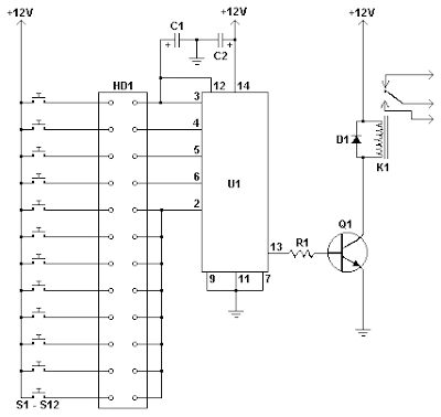
This simple circuit is the electronic version of the combination lock. Using the special purpose LS7220 digital lock IC, the circuit allows a 4 digit combination of your choice to activate a relay for a set period of time. This relay can then be used to trigger a lock solenoid, enable a starter button, open a motorized door, or many other tasks that require a momentary signal.Digital Keypad Combination Lock Circuit

Parts

Part
Total Qty.
Description
Substitutions
C111uF 25V Electrolytic Capacitor
C21220uF 25V Electrolytic Capacitor
R112.2K 1/4W Resistor
Q112N3904 NPN Transistor2N2222
D111N4148 Rectifier Diode1N4001-1N4007
K1112V SPDT RelayAny appropriate relay with 12V coil
U11LS7220 Digital Lock IC
S1-S1212SPST Momentary PushbuttonKeypad (see notes)
HD1112 Position Header

Notes

  1. To set the combination, wire the appropriate switches to U1 pins 3, 4, 5 and 6 using the header. For example if S1 was connected to pin 3, S2 to pin 4, S3 to pin 5 and S4 to pin 6, the combination would be 1,2,3,4. Now wire all other unused switches across the header to pin 2 of U1. In this way you can create any 4 digit combination you want. Pin 2 is the reset pin, so connecting all unused keys to it assures that the entire combination must be reentered if an incorrect key is pressed.
  2. When the appropriate combination is entered, the relay is activated for a period of time determined by C1. The 1uF capacitor specified in the parts list will result in an on-time of roughly 5 seconds. Increase the value of C1 to increase this time.
  3. An easy way to make a keypad is to buy 12 PC board mount pushbuttons and then etch a PC board so that the buttons are in 4 rows of 3, similar to a telephone keypad. Place this in a case and then use a label maker or transfer letters to add your numbers to the tops of the pushbuttons. You can also use a pre made keypad but keep in mind that you need a pad which provides an output for each key. Most pads available have the keys connected to provide a row and column signal when they are pressed.
Source: www.aaroncake.net
[Continue reading...]
 
Copyright © 2012. Fast Diagrams - Posts · Comments
Powered by Blogger