Showing posts with label an. Show all posts

Monday, October 13, 2014

An Alternative Pixie Known as The AP 80

- 0 comments

An

Overview

The project is an improved design of the Pixie which originally consists of an LM386 audio amp and just two transistors.

Explanation

The design of the circuit is very straightforward although it looks like complicated. A Colpitts crystal oscillator is the start of the circuit which uses a trimmer cap and 2N7000FET to provide a 600Hz frequency shift by adjusting the trimmer cap. Using a real mixer is the only way to fix the deficiencies of the Pixie. The transmitter low pass filter and receiver input is coupled with a classic series tuned C/L with diode limiting. The lower impedance input from the QSK network is coupled with the receiver input tuned circuit high impedance.

The transmitter is powered by 12V 1W supply as it consists of a 2N2222A buffer amp and a 2N7000. The Ac signal is kept coupled to the gate by the diode across the 2N7000 base. A PNP 2N3906 is added to the circuit to provide standard active low keying.

The receiver offset is the most critical adjustment which uses the C25 trimmer for control. The Rx inout trimmer is adjusted for best signal by attaching an antenna.

[Continue reading...]

Thursday, April 11, 2013

Making a Solar Energy Powered an iPhone Battery Charger

- 0 comments
The project was termed as Mighty Minty Boost as it was developed to function as iPod/iPhone charger with solar power. Aside from being small, it has a large battery capacity of 3.7V at 2000mAh and it accepts input power from 3.7V to 7V. As shown in the images below, it can become a compact USB power supply when the solar cell is removed after charging. The Velcro is used to secure the Mighty Minty Boost inside a backpack or messenger bag after unplugging the solar cell.

For faster charging, a larger solar cell can be attached to the bag. Enough power can be generated to fully charge an iPhone in about 5.5 hours and an iPod Touch in 4 hours using a slightly larger solar cell with 6V at 250mAh. The charger will automatically switch to trickle charging when the cell reaches full charge. The charging current is limited to 100mA when charging using the mini USB port and the charging is limited to 280mA when charging using the barrel plug jack

Hacks and Mods: iPhone Charger Powered Thru Solar Energy
.
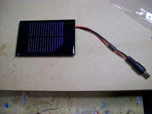
The materials needed to build the charger include a small solar cell, Lithium Polymer battery charger, minty boost kit, adhesive backed Velcro, Altoids tin, connector/wire, and small double adhesive squares as shown in the images below. An input power that ranges from 3.7V to 7V maximum can be accepted by the single cell Lithium Polymer. In bright sunlight, the solar cell maxes out at approximately 5V at 100mA. A larger solar cell with 6V at 250mA can be used for faster charging.

Hacks and Mods: iPhone Charger Powered Thru Solar Energy

The images below show the assembly of minty boost kit where a JST connector is soldered to the minty boost PCB instead of connecting the battery holder in the kit. The minty boost circuit is allowed to connect to the Lithium Polymer battery charger circuit with this tiny connector. The minty boost is tested by connecting the battery pack and the charger circuit, the Lithium Polymer battery connects to the connector marked GND on the charger board and the minty boost connects to the connector marked SYS.

Hacks and Mods: iPhone Charger Powered Thru Solar Energy

To fit the charger, a notch is cut out of the other side of the Altoids tin and used double sided adhesive to secure the charging circuit to the bottom of the Altoids as shown below. The bottom of either one of the circuit boards should not touch the bottom of the Altoids tin while reconnecting the minty boost PCB and the battery to the charging circuit.

Hacks and Mods: iPhone Charger Powered Thru Solar Energy

Connecting or adding the solar cell can be done in different ways. Shortening the connector leads and plugging the barrel plug into the barrel jack on the charging circuit is one way. The other method is using another JST connector to replace the connector and plugging it into the third connector marked 5V on the charging circuit. Since there is no bog barrel plug sticking out of the side of the tin, using the second method is cleaner.

As shown in the photos below, some 2” Velcro was used to attach the solar cell to the top of the Altoids. To help protect the battery, a layer of clear packing tape was used for wrapping. N top of the two circuit boards, the battery pack is then set down. A red LED on the charger board will light up when the Mighty Minty Boost is set out in the bright sun. The iPod/iPhone/USB powered device can be connected once it is fully charged.

Hacks and Mods: iPhone Charger Powered Thru Solar Energy
[Continue reading...]

Sunday, April 7, 2013

How to Modify an SMPS Circuit

- 0 comments
SMPS stands for switch mode power supply and its the modern and most compact/efficient way of acquiring low voltage DC from mains AC source. However making an SMPS at home may not be as simple as making power supply units using traditional iron core transformers. Also getting an SMPS with custom specs may not be that easy, in fact impossible if the voltage/current specs are far away from the regular values.


So does it mean that we have be satisfied with the SMPS specs which are typically set, and available in the market? For example how do we get an SMPS having an output of say 13 volts or 14 volts or 17 volts which are definitely not the normally accepted voltage ranges?

Since making such a customized unit may not be an easy task (due to complex layouts and part configurations) it would be a lot better if we could find ways of modifying a readymade one through some simple steps.

I have studied a few standard SMPS units and hopefully cracked ways of modifying the voltages and current as per individual choices. Lets learn it in details.

When you open any standard SMPS unit, you will come across the following things over the enclosed assembled card.

The populated PCB can be primarily divided into two sections by the presence of the center ferrite transformer.
The side of the transformer where the mains chord makes its entry is the input AC section while the other side from where the low voltage DC is derived is the DC section.

We are not interested in the AC section because we do not want to modify the input voltage so do not pay any attention there, moreover the AC section is POTENTIALLY VERY DANGEROUS TO TOUCH IN SWITCHED ON CONDITION, THEREFORE KEEPS YOUR HANDS OF IT WHILE TESTING.

The DC section will mainly consist of a couple of chokes, a couple of filter capacitors, a diode and a few other components.

Search for a transistor shaped component in this section. If you find a couple of them, one will be actually a transistor, probably for limiting the output current, however the other one will be definitely THE PROGRAMMABLE SHUNT REGULATOR.

This shunt regulator is the component which fixes the feedback voltage to the AC section mosfet and in turn determines the output voltage.

This programmable shunt device is set up through a couple of resistors, changing which will instantly change the output voltage as per ones wish.

Try to locate the resistors connected with the leads of this shunt device. One of them can be simply varied for changing the output voltage as per your preferences.

Take an external resistor of any value may be a 4k7 1/4 watt, now step-wise go on connecting this resistor across the resistors which are associated with the shunt regulator device.

Verify the output voltage each time you do the above step.

The moment you find a change in the output voltage either becoming low or high, you might have just found the one which we are looking for.

Now through some trial and error you may find out the exact value of resistor which could be replaced in place of the particular shunt resistor.

Thats it, its as simple as that, once you do it, the output voltage would get adjusted to that particular value permanently.

But do remember to remove the zener diode if theres any at the output of the power supply before you do the above procedures.


[Continue reading...]
 
Copyright © 2012. Fast Diagrams - Posts · Comments
Powered by Blogger