Showing posts with label schematic. Show all posts

Wednesday, October 29, 2014

Low Cost Universal Battery Charger Schematic

- 0 comments
This is the circuit diagram of a low cost universal charger for NiCD - NiMH batteries. This circuit is Ideal for car use. It has ability to transform a mains adapter in to a charger . This one can be used to charge cellular phone, toys, portables, video batteries, MP3 players, ... and has selectable charge current. An LED is located in circuit to indicate charging. Can be built on a general purpose PCB or a veroboard. I hope you really like it.

Picture of the circuit:

 a_low_cost_universal_charger 
 A Low Cost Universal Charger Circuit Schematic
Circuit diagram:
a_low_cost_universal_charger_circuit_diagram_for_nicd
A Low Cost Universal Charger Circuit Diagram


Parts:
R1 = 120R-0...5W
R2 = See Diagram
C1 = 220uF-35V
D1 = 1N4007
D2 = 3mm. LED
Q1 = BD135
J1 = DC Input Socket
Specifications:
  • Ideal for in car use.
  • LED charge indication.
  • Selectable charge current.
  • Charges Ni Cd or NiMH batteries.
  • Transforms a mains adapter into a charger.
  • Charge cellular phone, toys, portables, video batteries …
Features:
  • LED function indication.
  • Power supply polarity protected.
  • Supply current: same as charge current.
  • Supply voltage: from 6.5VDC to 21VDC (depending on used battery)
  • Charge current (±20%): 50mA, 100mA, 200mA, 300mA, 400mA. (selectable)
Determining the supply voltage:
This table indicates the minimum and maximum voltages to supply the charger. See supply voltage selection chart below.
Example:
To charge a 6V battery a minimum supply voltage of 12V is needed, the maximum voltage is then 15V.
Voltage selection:

supply_voltages_selection_chart_for_
Voltage Selection Chart For Low Cost Universal Battery Charger

Determining the charge current:
Before building the circuit, you must determinate how much current will be used to charge the battery or battery pack. It is advisable to charge the battery with a current that is 10 times smaller then the battery capacity, and to charge it for about 15 hours. If you double the charge current , then you can charge the battery in half the time. Charge current selection chart is located in diagram.

Example:
A battery pack of 6V / 1000mAh can be charged with 100mA during 15 hours. If you want to charge faster, then a charge current of 200mA can be used for about 7 hours.
Caution:
The higher charge current, the more critical the charge time must be checked. When faster charging is used, it is advisable to discharge the battery completely before charging. Using a charge current of 1/10 of the capacity will expand the lifetime of the battery. The charge time can easily be doubled without damaging the battery.
Note:
  • Mount the transistor together with the heatsink on the PCB, bend the leads as necessary. Take care that the metal back of the transistor touches the heatsink. Check that the leads of the transistor do not touch the heatsink.
[Continue reading...]

Thursday, October 16, 2014

12V to 120V DC DC Converter Circuit

- 0 comments

12V to 120V DC DC Converter Circuit

Here is a simple DC DC converter schematic using a saturation-limited to push-pull converter. DC converter can be used to power the VCR from a car battery and glow plug light aircraft models from a 12V battery starter.

As a final amplifier of the DC DC converter is a pair of transistor MJE2955 and 2SC945 as oscillator to apply sufficient bias to the final amplifier transistors.

The 2SC945 is a bias switch for startup. When applying 12V power, this transistor applies enough bias to the power transistors to get the oscillation started. Soon later, the 100uF capacitor charges up, the transistor goes off, and the power transistors self-bias into cut-off, such that cross-conduction is eliminated. After removing power, the 6k8 resistor discharges the bias timing capacitor, as otherwise the circuit would be unable to restart!

The secondary rectifiers are ultrafast diodes. These are NOT 1N4007! And the 220nF capacitors for the secondary filter are no typos; the diodes deliver almost pure DC, since the oscillation waveform is square, so only some noise filtering is needed. No electrolytics are necessary here.

12V

DC DC Converter

Note the filters at both input and output, using ferrite cores. These are necessary to avoid polluting your environment with RF noise! Using these filters, and joining the input and output negative leads, this converter is very quiet and does not cause any problem in my combined HF, VHF and UHF station.

All ferrite cores (for the transformer and for the noise filters) are manufactured by Amidon Associates, and can be ordered directly from them in small quantities. Look for Amidon on the web. The 77-material core used for the transformer is less than ideal. A square-loop ferrite would work more efficiently! This one gets really warm, operating in saturation mode at 25 kHz. But it has worked well enough for two years now. The filter cores, on the other hand, are well chosen, so try to use the exact ones.

For all windings, the schematic states the number of turns. “7t” means 7 turns. As the transformer is quite small for the involved power, use as thick a wire as you can fit, leaving about half of the space for the 2×7 turns primary winding, and the other half for the secondary, while the feedback winding can be made from very thin wire.

The transistors do not need any heat sinks. They are large enough without, and they need to dissipate little heat!

[Continue reading...]

Friday, September 19, 2014

VIEWSONIC G90fB 4 Model No VS10794 19” Digital Controlled Color Monitor Schematic Full

- 0 comments
Viewsonic G90fB-4 Model No. VS10794 - 19” Digital Controlled Color Monitor_Circuit Diagram_[Full]
CPU 
SMPS
OUTPUT
VIDEO

[Continue reading...]

Friday, September 5, 2014

50W car audio amplifier schematic circuits

- 0 comments
50WCar power amplifier uses SI1050GL IC as the main amplifier. The output power 50 Watt 8 ohm mono impedance. Up to 25 Volt DC voltage. with source voltage of this amplifier car battery has to work.


Minimum of 12 Volt battery voltage, less than a sound or audio is issued less than the maximum and less good. You can assemble  this circuit amplifier with a schema like this.
50W
Part List
R1 = 100K
R2 = 1R
C1 = 2.2uF
C2 = 22uF
C3 = 100uF
C4 = 0.1uF
C5 = 100uF
U1 = SI1050GL
If you want to make stereo amplifier , you must required multiply the two of components. 


[Continue reading...]

Wednesday, June 12, 2013

Digital Keypad Combination Lock Circuit Schematic with explanation

- 0 comments
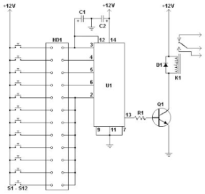
This simple circuit is the electronic version of the combination lock. Using the special purpose LS7220 digital lock IC, the circuit allows a 4 digit combination of your choice to activate a relay for a set period of time. This relay can then be used to trigger a lock solenoid, enable a starter button, open a motorized door, or many other tasks that require a momentary signal.Digital Keypad Combination Lock Circuit

Parts

Part
Total Qty.
Description
Substitutions
C111uF 25V Electrolytic Capacitor
C21220uF 25V Electrolytic Capacitor
R112.2K 1/4W Resistor
Q112N3904 NPN Transistor2N2222
D111N4148 Rectifier Diode1N4001-1N4007
K1112V SPDT RelayAny appropriate relay with 12V coil
U11LS7220 Digital Lock IC
S1-S1212SPST Momentary PushbuttonKeypad (see notes)
HD1112 Position Header

Notes

  1. To set the combination, wire the appropriate switches to U1 pins 3, 4, 5 and 6 using the header. For example if S1 was connected to pin 3, S2 to pin 4, S3 to pin 5 and S4 to pin 6, the combination would be 1,2,3,4. Now wire all other unused switches across the header to pin 2 of U1. In this way you can create any 4 digit combination you want. Pin 2 is the reset pin, so connecting all unused keys to it assures that the entire combination must be reentered if an incorrect key is pressed.
  2. When the appropriate combination is entered, the relay is activated for a period of time determined by C1. The 1uF capacitor specified in the parts list will result in an on-time of roughly 5 seconds. Increase the value of C1 to increase this time.
  3. An easy way to make a keypad is to buy 12 PC board mount pushbuttons and then etch a PC board so that the buttons are in 4 rows of 3, similar to a telephone keypad. Place this in a case and then use a label maker or transfer letters to add your numbers to the tops of the pushbuttons. You can also use a pre made keypad but keep in mind that you need a pad which provides an output for each key. Most pads available have the keys connected to provide a row and column signal when they are pressed.
Source: www.aaroncake.net
[Continue reading...]

Wednesday, May 29, 2013

Typical Trailer Wiring Diagramcircuit Schematic

- 0 comments
Electrical Wiring Diagrams on Free Wiring Diagrams   Download Free Wiring Schematics
Free Wiring Diagrams Download Free Wiring Schematics.


Electrical Wiring Diagrams on Series 600 Electric Wiring Diagram   Car Parts And Wiring Diagram
Series 600 Electric Wiring Diagram Car Parts And Wiring Diagram.


Electrical Wiring Diagrams on Wiring Diagram
Wiring Diagram.


Electrical Wiring Diagrams on Automotive Electrical Diagrams Provide Symbols That Represent Circuit
Automotive Electrical Diagrams Provide Symbols That Represent Circuit.


Electrical Wiring Diagrams on Residential Circuit Diagram Electrical Wiring Information
Residential Circuit Diagram Electrical Wiring Information.


Electrical Wiring Diagrams on 1964 Gmc Truck Electrical System Wiring Diagram   Circuit Schematic
1964 Gmc Truck Electrical System Wiring Diagram Circuit Schematic.


Electrical Wiring Diagrams on Free Wiring Diagrams   Download Free Wiring Schematics
Free Wiring Diagrams Download Free Wiring Schematics.


Electrical Wiring Diagrams on Honda Goldwing Gl1100 Wiring Diagram And Electrical System Harness
Honda Goldwing Gl1100 Wiring Diagram And Electrical System Harness.


Electrical Wiring Diagrams on Typical 7 Way Trailer Wiring Diagram   Circuit Schematic
Typical 7 Way Trailer Wiring Diagram Circuit Schematic.


Electrical Wiring Diagrams on Standard Electric Water Heater Operation
Standard Electric Water Heater Operation.


[Continue reading...]

Friday, April 12, 2013

Simple Ignition Timer Schematic

- 0 comments
This circuit is a tester for flywheel based ignition systems in small aeroplane engines. Basically the same ignition coils are also seen in other small combustion engines used in/on mopeds and lawn mowers  in brief, engines without a battery. The part to be tested comprises a primary coil in parallel with the contact breaker. The timing of this contact breaker has to be adjusted correctly.
Since the coil’s primary has a very low resistance it is difficult to determine whether the contact breaker is open or closed.  However, you can determine that reliably with this circuit, using an LED and a beeper. The circuit is implemented twice because aviation engines (Cessna, Piper and similar) always have two ignitions in parallel to increase reliability. For two-cylinder engines, well the purpose is obvious.
Ignition Timer Circuit Diagram
The circuit consists of a 555 and a few transistors. The 555 supplies a square wave of about 3000 Hz. This signal goes to power transistors T1 and T2; these can supply quite a bit of power and are robust enough to withstand the voltage transients from the big coils. The test connection (K2 and K3 respectively) are connected in parallel with the contact breaker to be tested, which itself is in parallel with the ignition coil. The frequency of 3000 Hz is either short circuited by the contact breaker or if the points are open  is amplified somewhat by the resonance of the coil itself.

This allows you to reliably detect the difference bet ween a closed and open contact breaker, despite the low resistance of the coil, which is in parallel with it. When the contact breaker is open the amplified pulses will turn on T3 and T4 respectively, so that the relevant LEDs turn on and the buzzer will sound.

The components are not critical, but do use a sensitive type for the piezo buzzer. The power supply is 3 V (2 times AA or AAA batteries). Link
[Continue reading...]

Thursday, April 11, 2013

TA7230P TA7236P TA7237AP amplifier schematic

- 0 comments
Amplifier circuit here is all based on the ic in the gains. Three IC TA7230P, TA7236P, TA7237AP is intregated circuit (IC) which was applied to the power amplifier. Each IC has a different output, different input voltage, all IC TA7230P, TA7236P, TA7237AP is manufactured by Toshiba.

You can see maximum minimum voltage , power output , and other here
TA7230P, TA7236P, TA7237AP amplifier schematic
[Continue reading...]
 
Copyright © 2012. Fast Diagrams - Posts · Comments
Powered by Blogger